Cirkit Designer Logo
Cirkit Designer
Your all-in-one circuit design IDE
Home / 
Component Documentation

How to Use Adafruit ADXL377: Examples, Pinouts, and Specs

Image of Adafruit ADXL377
Cirkit Designer LogoDesign with Adafruit ADXL377 in Cirkit Designer

Introduction

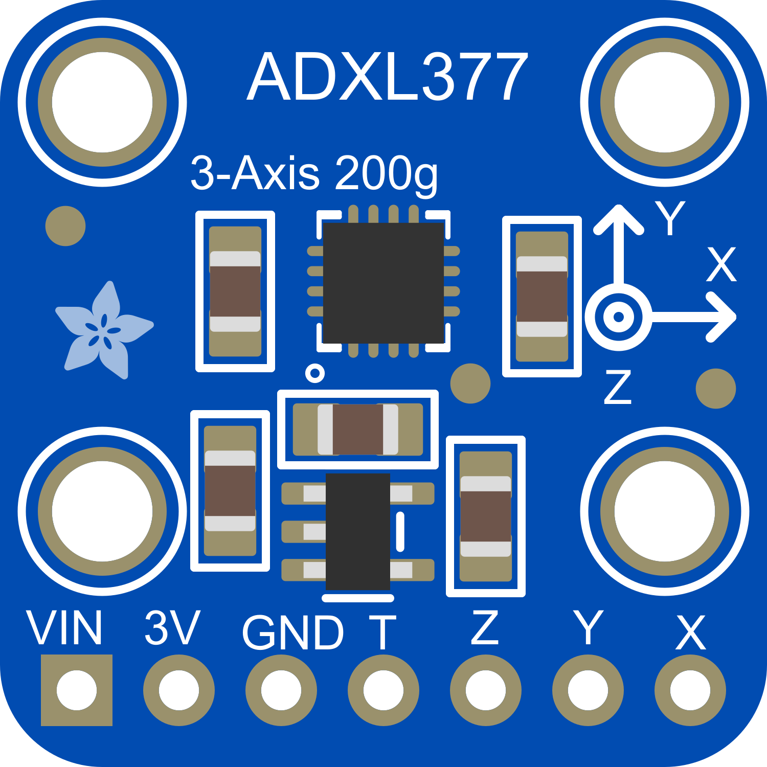
The Adafruit ADXL377 is a high-resolution, low-power, 3-axis accelerometer module capable of measuring acceleration up to ±200g. This makes it an ideal choice for a wide range of applications, including tilt sensing, impact detection, and motion control in both consumer electronics and industrial systems. Its high-g range allows it to be used in environments with extreme dynamic motion, such as sports equipment or vehicle crash analysis.

Explore Projects Built with Adafruit ADXL377

Use Cirkit Designer to design, explore, and prototype these projects online. Some projects support real-time simulation. Click "Open Project" to start designing instantly!
ESP32-Based 3-Axis Accelerometer Data Logger
Image of adxl337: A project utilizing Adafruit ADXL377 in a practical application
This circuit connects an ESP32 microcontroller to an Adafruit ADXL377 accelerometer. The ESP32 reads acceleration data along the X, Y, and Z axes from the ADXL377 via its D32, D33, and D34 pins, respectively. The circuit is likely intended for motion or orientation sensing applications, with the ESP32 processing and possibly transmitting the accelerometer data for further use.
Cirkit Designer LogoOpen Project in Cirkit Designer
Arduino UNO and ADXL345 Accelerometer Data Logger
Image of Accelerometer ADXL345 Circuit Diagram: A project utilizing Adafruit ADXL377 in a practical application
This circuit features an Arduino UNO microcontroller interfaced with an Adafruit ADXL345 accelerometer for motion detection, powered by two parallel-connected 18650 Li-ion batteries. The accelerometer communicates with the Arduino over I2C, and the system is designed for further code development to utilize the motion sensing capabilities.
Cirkit Designer LogoOpen Project in Cirkit Designer
Arduino UNO with Adafruit ADXL345 Accelerometer Data Logger
Image of ADXL345: A project utilizing Adafruit ADXL377 in a practical application
This circuit connects an Arduino UNO microcontroller with an Adafruit ADXL345 accelerometer sensor. The Arduino powers the sensor, communicates with it via I2C (using pins A4 and A5 for SDA and SCL respectively), and runs a program to read and output the acceleration data in three axes. The purpose of the circuit is to measure acceleration and provide real-time data for analysis or further processing.
Cirkit Designer LogoOpen Project in Cirkit Designer
Arduino Leonardo and ADXL345 Accelerometer-Based Motion Detection System
Image of mini project: A project utilizing Adafruit ADXL377 in a practical application
This circuit interfaces an ADXL345 accelerometer with an Arduino Leonardo via I2C communication. The Arduino provides power and ground to the accelerometer and reads acceleration data through the SDA and SCL lines.
Cirkit Designer LogoOpen Project in Cirkit Designer

Explore Projects Built with Adafruit ADXL377

Use Cirkit Designer to design, explore, and prototype these projects online. Some projects support real-time simulation. Click "Open Project" to start designing instantly!
Image of adxl337: A project utilizing Adafruit ADXL377 in a practical application
ESP32-Based 3-Axis Accelerometer Data Logger
This circuit connects an ESP32 microcontroller to an Adafruit ADXL377 accelerometer. The ESP32 reads acceleration data along the X, Y, and Z axes from the ADXL377 via its D32, D33, and D34 pins, respectively. The circuit is likely intended for motion or orientation sensing applications, with the ESP32 processing and possibly transmitting the accelerometer data for further use.
Cirkit Designer LogoOpen Project in Cirkit Designer
Image of Accelerometer ADXL345 Circuit Diagram: A project utilizing Adafruit ADXL377 in a practical application
Arduino UNO and ADXL345 Accelerometer Data Logger
This circuit features an Arduino UNO microcontroller interfaced with an Adafruit ADXL345 accelerometer for motion detection, powered by two parallel-connected 18650 Li-ion batteries. The accelerometer communicates with the Arduino over I2C, and the system is designed for further code development to utilize the motion sensing capabilities.
Cirkit Designer LogoOpen Project in Cirkit Designer
Image of ADXL345: A project utilizing Adafruit ADXL377 in a practical application
Arduino UNO with Adafruit ADXL345 Accelerometer Data Logger
This circuit connects an Arduino UNO microcontroller with an Adafruit ADXL345 accelerometer sensor. The Arduino powers the sensor, communicates with it via I2C (using pins A4 and A5 for SDA and SCL respectively), and runs a program to read and output the acceleration data in three axes. The purpose of the circuit is to measure acceleration and provide real-time data for analysis or further processing.
Cirkit Designer LogoOpen Project in Cirkit Designer
Image of mini project: A project utilizing Adafruit ADXL377 in a practical application
Arduino Leonardo and ADXL345 Accelerometer-Based Motion Detection System
This circuit interfaces an ADXL345 accelerometer with an Arduino Leonardo via I2C communication. The Arduino provides power and ground to the accelerometer and reads acceleration data through the SDA and SCL lines.
Cirkit Designer LogoOpen Project in Cirkit Designer

Technical Specifications

Key Features

  • Measurement Range: ±200g on all three axes (X, Y, Z)
  • Resolution: High resolution at low noise
  • Supply Voltage: 3.3V to 5V
  • Output: Analog voltage output for each axis
  • Bandwidth: Selectable between 100Hz and 1kHz
  • Temperature Range: -40°C to +85°C

Pin Configuration and Descriptions

Pin Number Name Description
1 GND Ground connection for the power supply
2 VCC Supply voltage (3.3V to 5V)
3 X-OUT Analog voltage output for the X-axis
4 Y-OUT Analog voltage output for the Y-axis
5 Z-OUT Analog voltage output for the Z-axis
6 SELF_TEST Self-test pin (typically not used for normal operation)

Usage Instructions

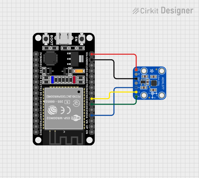
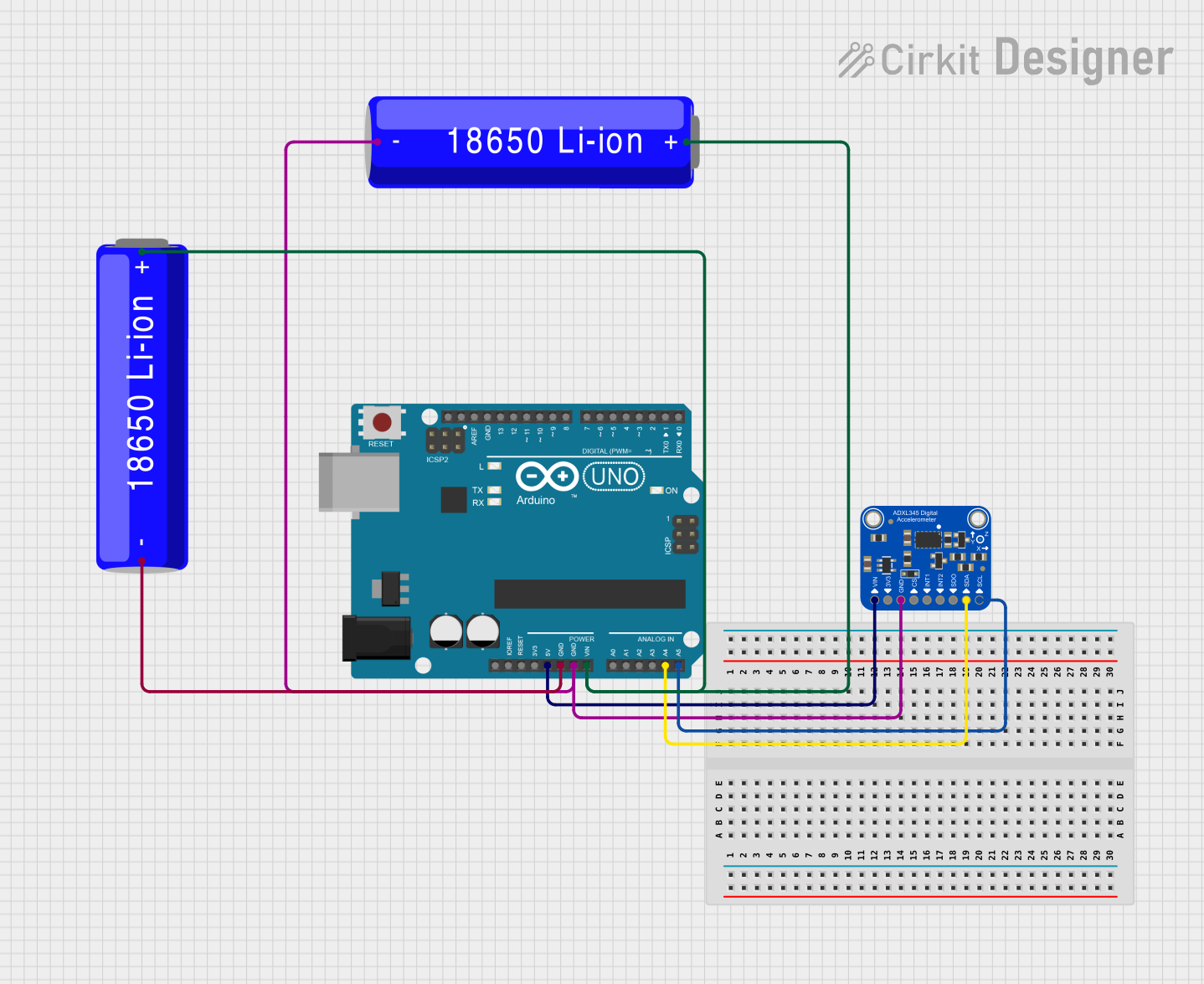
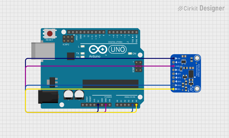
Integration into a Circuit

To use the ADXL377 in a circuit:

  1. Connect the VCC pin to a 3.3V or 5V power supply.
  2. Connect the GND pin to the ground of the power supply.
  3. Connect the X-OUT, Y-OUT, and Z-OUT pins to the analog inputs of a microcontroller, such as an Arduino UNO, to read the acceleration values.

Best Practices

  • Use a clean and stable power supply to minimize noise in the acceleration readings.
  • Keep the analog signal paths as short as possible to reduce susceptibility to electromagnetic interference.
  • Apply proper filtering techniques to the output signals to improve measurement accuracy.
  • Secure the module firmly to the object whose acceleration is being measured to ensure accurate readings.

Example Code for Arduino UNO

// Include the Arduino core library
#include <Arduino.h>

// Define the analog pins connected to the accelerometer outputs
const int xPin = A0;
const int yPin = A1;
const int zPin = A2;

void setup() {
  // Initialize serial communication at 9600 baud rate
  Serial.begin(9600);
}

void loop() {
  // Read the raw values from the accelerometer
  int xRaw = analogRead(xPin);
  int yRaw = analogRead(yPin);
  int zRaw = analogRead(zPin);

  // Convert the raw values to 'g' values
  // Assuming a 5V supply, 1g is approximately 0.33V or 67.5 on a 10-bit ADC
  float xG = (xRaw - 512) / 67.5;
  float yG = (yRaw - 512) / 67.5;
  float zG = (zRaw - 512) / 67.5;

  // Print the acceleration values in 'g' for each axis
  Serial.print("X: ");
  Serial.print(xG);
  Serial.print("g, Y: ");
  Serial.print(yG);
  Serial.print("g, Z: ");
  Serial.print(zG);
  Serial.println("g");

  // Delay for a short period to avoid spamming the serial output
  delay(100);
}

Troubleshooting and FAQs

Common Issues

  • Inaccurate Readings: Ensure that the power supply is stable and that the accelerometer is securely mounted.
  • No Output Signal: Check the connections to the analog pins and verify that the power supply is within the specified range.
  • Noise in Signal: Keep the analog signal paths short and consider using shielded cables.

FAQs

Q: Can the ADXL377 be used with a 3.3V system? A: Yes, the ADXL377 can operate with a supply voltage from 3.3V to 5V.

Q: How can I calibrate the accelerometer? A: Calibration involves taking readings at known orientations and adjusting the output to match the expected 'g' values.

Q: What is the purpose of the SELF_TEST pin? A: The SELF_TEST pin is used to verify the functionality of the accelerometer by producing a known output signal.

For further assistance, consult the Adafruit ADXL377 datasheet and application notes provided by the manufacturer.