How to Use Watt Meter AC: Examples, Pinouts, and Specs
Introduction
A Watt Meter AC is a device used to measure the power consumption of AC electrical devices, displaying the power in watts. It is an essential tool for monitoring energy usage, optimizing power efficiency, and diagnosing electrical issues. Watt meters are commonly used in residential, commercial, and industrial settings to track energy consumption and ensure devices operate within their rated power limits.
Explore Projects Built with Watt Meter AC
Explore Projects Built with Watt Meter AC
Common Applications and Use Cases
- Monitoring household appliance power consumption.
- Measuring energy usage in industrial equipment.
- Testing and troubleshooting electrical devices.
- Optimizing energy efficiency in renewable energy systems.
- Educational purposes in electronics and electrical engineering labs.
Technical Specifications
Below are the general technical specifications for a typical Watt Meter AC. Note that actual specifications may vary depending on the model and manufacturer.
Key Technical Details
| Parameter | Value |
|---|---|
| Input Voltage Range | 100V AC to 250V AC |
| Frequency Range | 50Hz to 60Hz |
| Power Measurement Range | 0.1W to 3680W (varies by model) |
| Accuracy | ±1% |
| Display Type | LCD or LED |
| Operating Temperature | -10°C to 50°C |
| Storage Temperature | -20°C to 60°C |
| Power Supply | Self-powered (via AC input) |
Pin Configuration and Descriptions
Most Watt Meters AC are standalone devices and do not have pins for external connections. However, for models with additional features (e.g., communication interfaces), the pin configuration may look like this:
| Pin Name | Description |
|---|---|
| L (Live) | Connects to the live wire of the AC source. |
| N (Neutral) | Connects to the neutral wire of the AC source. |
| GND | Ground connection (if applicable). |
| TX (Optional) | Transmit data for communication (e.g., UART). |
| RX (Optional) | Receive data for communication (e.g., UART). |
Usage Instructions
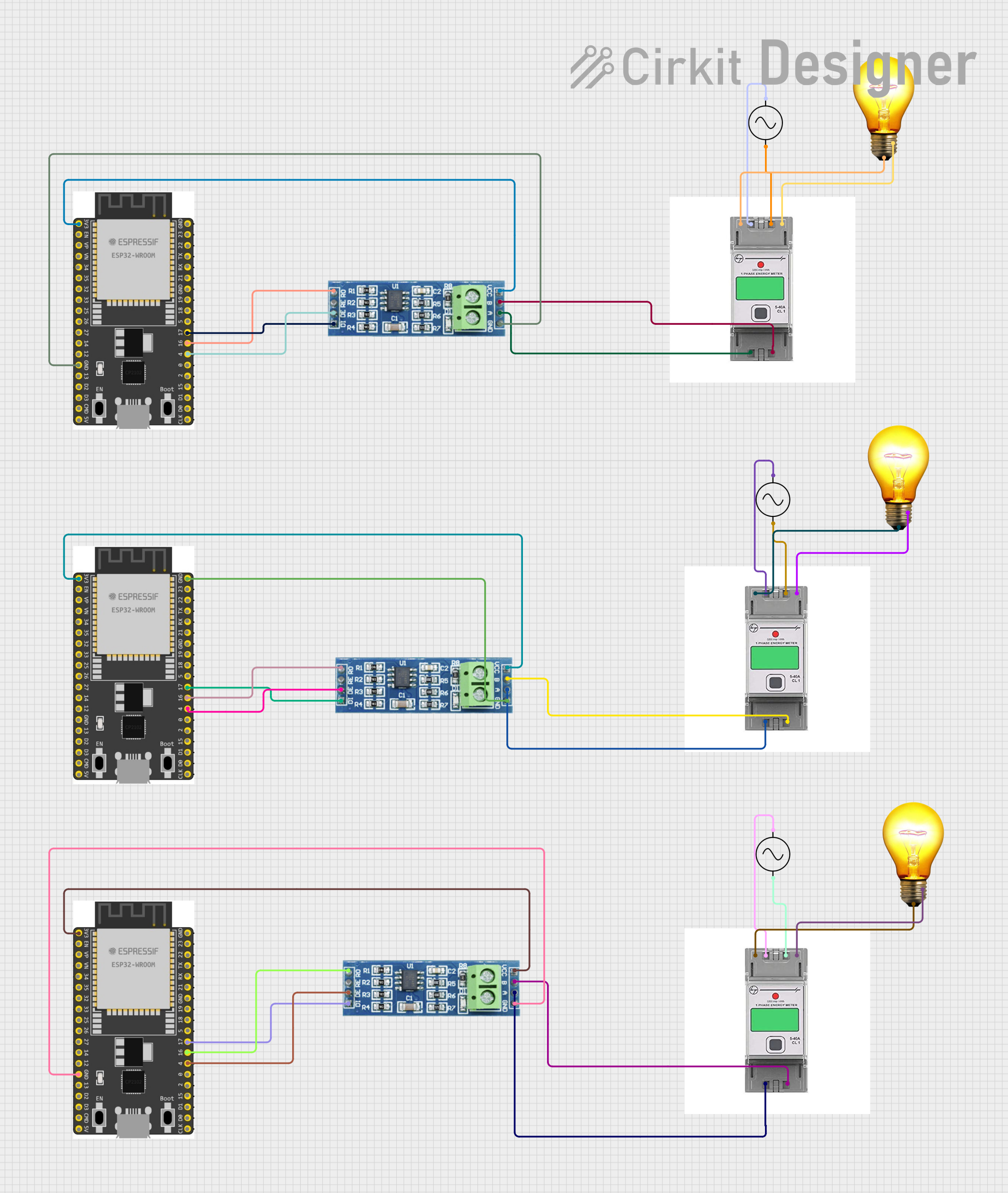
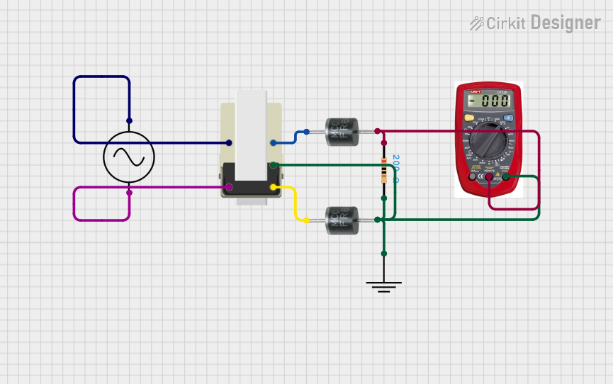
How to Use the Watt Meter AC in a Circuit
Connect the Watt Meter AC to the Power Source:
- Identify the live (L) and neutral (N) wires of the AC power source.
- Connect the live wire to the "L" terminal and the neutral wire to the "N" terminal of the watt meter.
- If the watt meter has a ground terminal, connect it to the ground wire.
Connect the Load:
- Plug the electrical device (load) into the output socket of the watt meter (if available).
- Alternatively, wire the load directly to the output terminals of the watt meter.
Power On:
- Turn on the AC power source. The watt meter will display the power consumption of the connected load in real-time.
Read the Measurements:
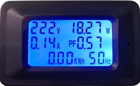
- Observe the displayed values, which may include power (W), voltage (V), current (A), and energy consumption (kWh), depending on the model.
Important Considerations and Best Practices
- Voltage and Current Ratings: Ensure the watt meter is rated for the voltage and current of your AC source and load.
- Safety Precautions: Always disconnect power before wiring the watt meter to avoid electric shock.
- Calibration: Periodically calibrate the watt meter for accurate measurements, especially in critical applications.
- Environmental Conditions: Avoid using the watt meter in extreme temperatures or high-humidity environments.
- Communication Features: If the watt meter supports data communication (e.g., UART), refer to the manufacturer's documentation for setup instructions.
Example: Using a Watt Meter AC with Arduino UNO
Some advanced Watt Meters AC support UART communication for data logging. Below is an example of how to interface such a watt meter with an Arduino UNO.
#include <SoftwareSerial.h>

// Define RX and TX pins for communication with the Watt Meter
SoftwareSerial wattMeterSerial(10, 11); // RX = Pin 10, TX = Pin 11

void setup() {
  Serial.begin(9600); // Initialize Serial Monitor
  wattMeterSerial.begin(9600); // Initialize Watt Meter communication

  Serial.println("Watt Meter AC Data Logger");
}

void loop() {
  // Check if data is available from the Watt Meter
  if (wattMeterSerial.available()) {
    String wattMeterData = ""; // Variable to store incoming data

    // Read data from the Watt Meter
    while (wattMeterSerial.available()) {
      char c = wattMeterSerial.read();
      wattMeterData += c;
    }

    // Print the received data to the Serial Monitor
    Serial.println("Watt Meter Data: " + wattMeterData);
  }

  delay(1000); // Wait for 1 second before reading again
}
Notes:
- Replace
10and11with the appropriate pins for your setup. - Ensure the watt meter's communication protocol matches the Arduino's settings (e.g., baud rate).
Troubleshooting and FAQs
Common Issues and Solutions
| Issue | Possible Cause | Solution |
|---|---|---|
| No display or power on the meter. | Incorrect wiring or no power supply. | Verify connections and ensure power is on. |
| Inaccurate readings. | Calibration drift or electrical noise. | Recalibrate the meter or reduce noise. |
| Communication not working (UART). | Incorrect baud rate or wiring. | Check baud rate and wiring connections. |
| Overload warning. | Load exceeds meter's rated capacity. | Reduce the load to within rated limits. |
FAQs
Can I use a Watt Meter AC with a DC power source?
- No, Watt Meters AC are designed specifically for alternating current (AC). For DC measurements, use a DC watt meter.
How do I reset the energy consumption (kWh) reading?
- Most watt meters have a reset button or menu option. Refer to the user manual for specific instructions.
Can I use the Watt Meter AC outdoors?
- Only if it is rated for outdoor use. Otherwise, protect it from moisture and extreme temperatures.
What happens if I exceed the watt meter's rated power?
- The meter may display an overload warning or shut down to prevent damage. Always stay within the specified limits.
By following this documentation, you can effectively use a Watt Meter AC to monitor and optimize your energy usage.