How to Use Pushbutton (SIM TEST): Examples, Pinouts, and Specs
Introduction
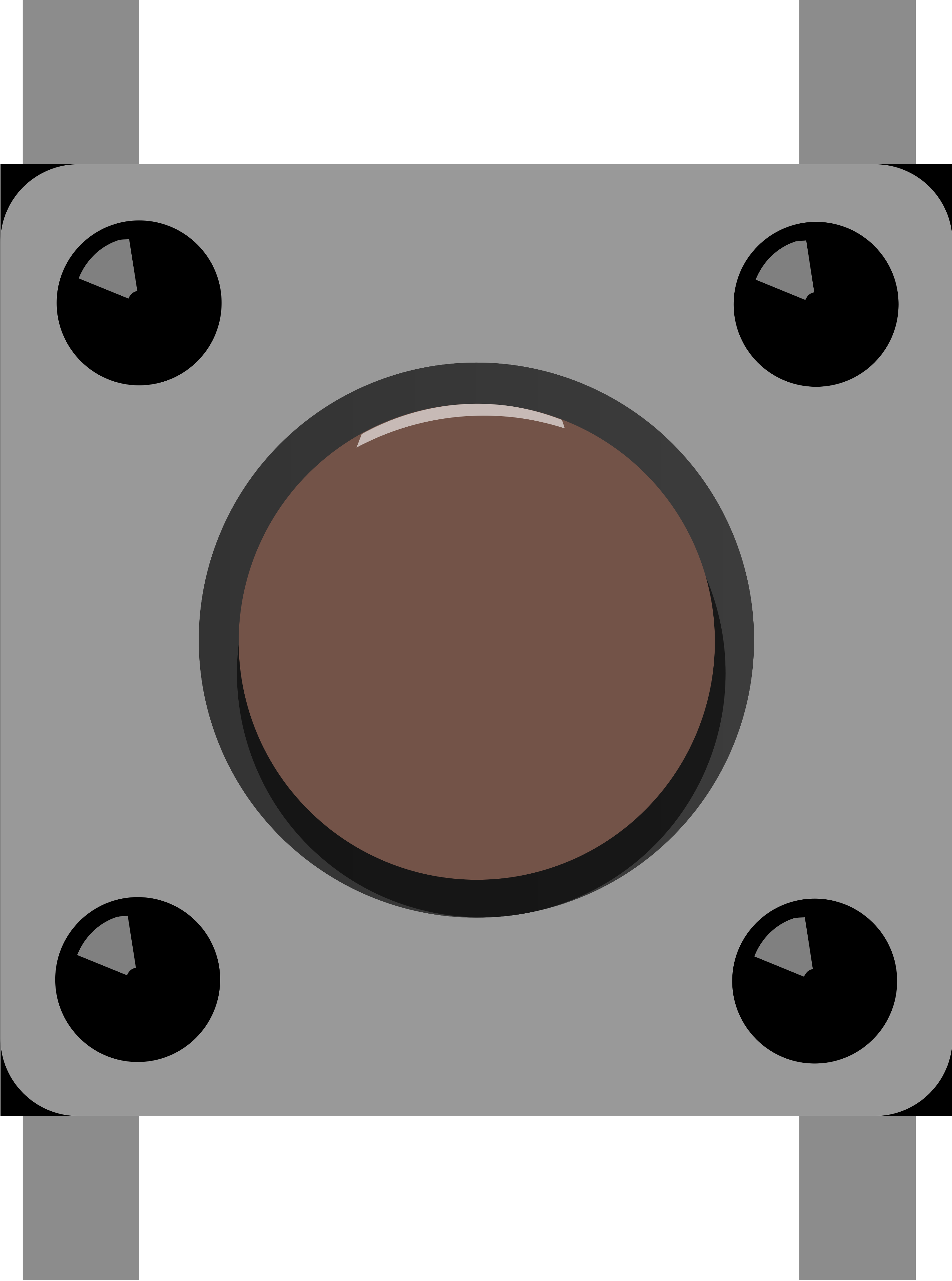
The Pushbutton (SIM TEST) is a momentary switch designed to complete a circuit temporarily. This component is widely used in various applications, particularly in testing scenarios where simulating user input or resetting devices is required. Its simple operation makes it an essential tool for engineers, hobbyists, and developers alike.
Explore Projects Built with Pushbutton (SIM TEST)
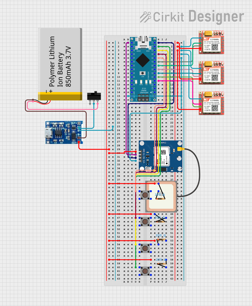
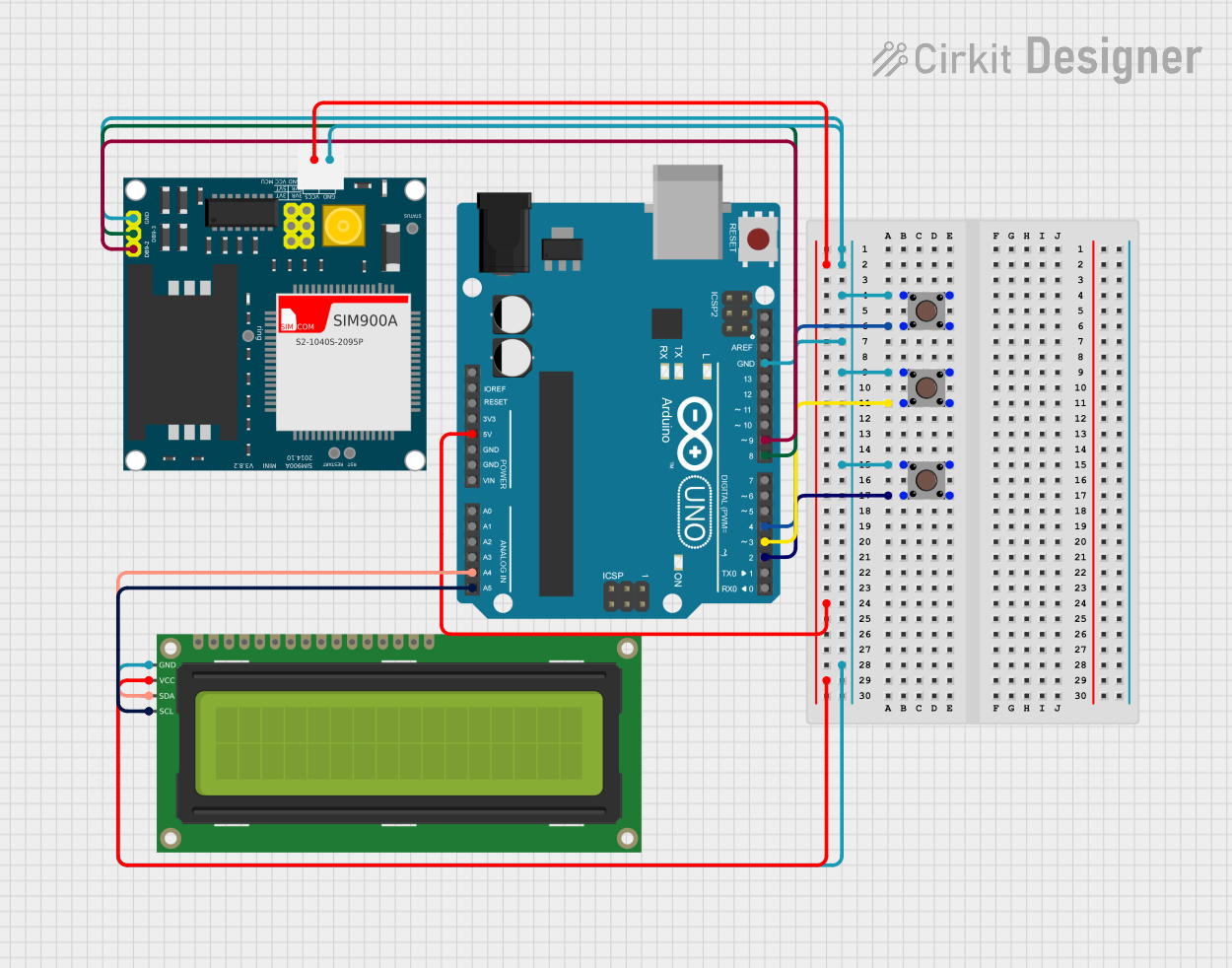
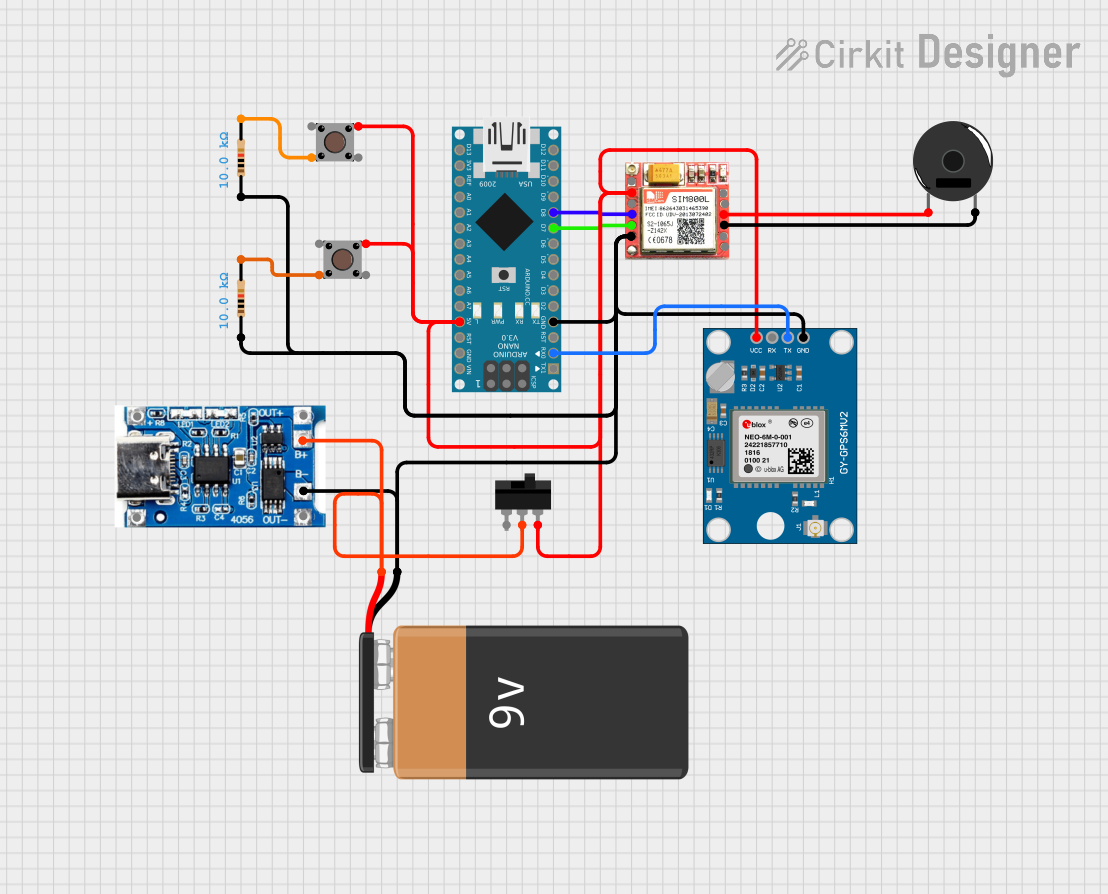
Explore Projects Built with Pushbutton (SIM TEST)
Common Applications and Use Cases
- Testing Circuits: Used to simulate user input during circuit testing.
- Resetting Devices: Acts as a reset switch for microcontrollers and other devices.
- User Interfaces: Provides a simple interface for user interaction in prototypes.
- Debugging: Helps in troubleshooting by allowing manual control of circuit states.
Technical Specifications
Key Technical Details
| Specification | Value |
|---|---|
| Voltage Rating | 12V DC |
| Current Rating | 10A |
| Power Rating | 120W |
| Contact Type | Normally Open (NO) |
| Actuation Force | 200g (approx.) |
| Lifespan | 1,000,000 cycles |
Pin Configuration and Descriptions
| Pin Number | Pin Name | Description |
|---|---|---|
| 1 | COM | Common terminal for the switch |
| 2 | NO | Normally Open terminal |
Usage Instructions
How to Use the Component in a Circuit
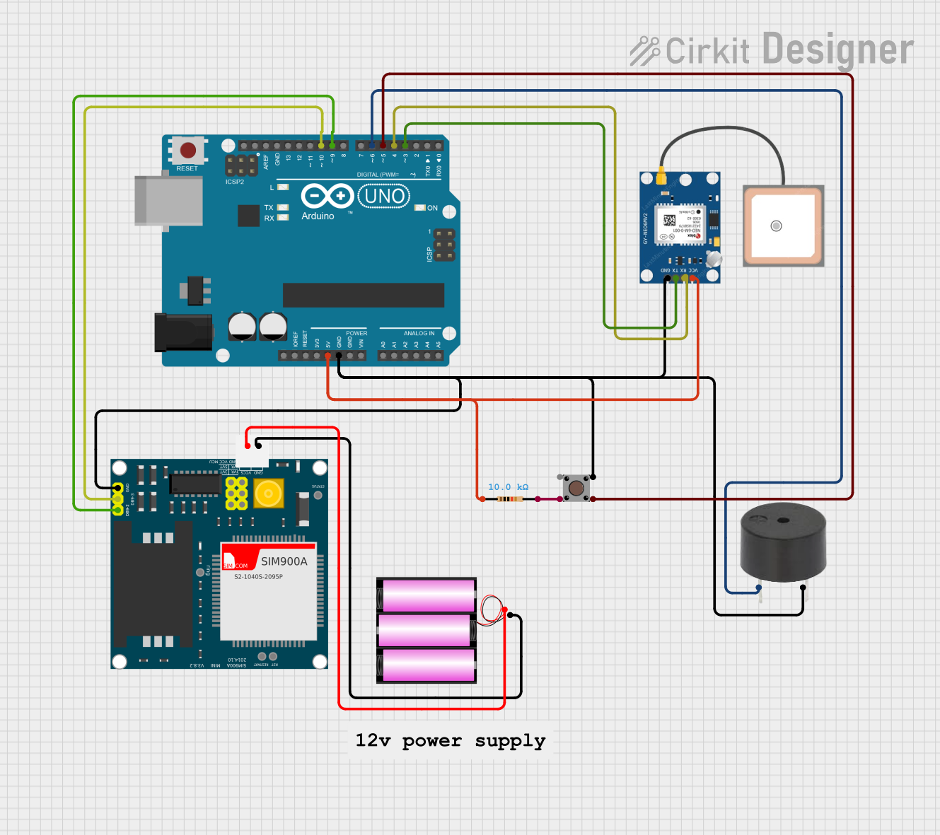
Wiring the Pushbutton:
- Connect one terminal (COM) to the ground (GND) of your circuit.
- Connect the Normally Open (NO) terminal to the input pin of your microcontroller or circuit.
Circuit Example:
- For an Arduino UNO, you can connect the pushbutton to digital pin 2.
Important Considerations and Best Practices
- Debouncing: When using the pushbutton in digital circuits, consider implementing a debouncing mechanism to avoid false triggering due to mechanical bounce.
- Pull-up Resistor: Use a pull-up resistor (typically 10kΩ) to ensure a stable HIGH state when the button is not pressed.
- Voltage Ratings: Ensure that the voltage and current ratings of the pushbutton are not exceeded to prevent damage.
Troubleshooting and FAQs
Common Issues Users Might Face
Button Not Responding:
- Ensure that the wiring is correct and that the button is properly connected.
- Check for any loose connections or broken wires.
False Triggering:
- This may be due to mechanical bounce. Implement debouncing in your code or circuit.
Button Sticking:
- Inspect the button for any physical obstructions or damage.
Solutions and Tips for Troubleshooting
- Testing with a Multimeter: Use a multimeter to check continuity across the pushbutton terminals when pressed.
- Code Example for Arduino UNO:
const int buttonPin = 2; // Pin connected to the pushbutton
int buttonState = 0;     // Variable to store button state

void setup() {
    pinMode(buttonPin, INPUT_PULLUP); // Set pin as input with pull-up
    Serial.begin(9600);                // Start serial communication
}

void loop() {
    // Read the state of the pushbutton
    buttonState = digitalRead(buttonPin);
    if (buttonState == LOW) { // Button pressed
        Serial.println("Button Pressed!");
        delay(200); // Debounce delay
    }
}
This code sets up the pushbutton on pin 2 of the Arduino UNO, using the internal pull-up resistor. When the button is pressed, it prints a message to the serial monitor. Adjust the delay as needed for your application.
By following this documentation, users can effectively utilize the Pushbutton (SIM TEST) in their projects, ensuring reliable performance and ease of use.