
How to Use SparkFun ISD1932 Voice Recorder Breakout v1.1: Examples, Pinouts, and Specs
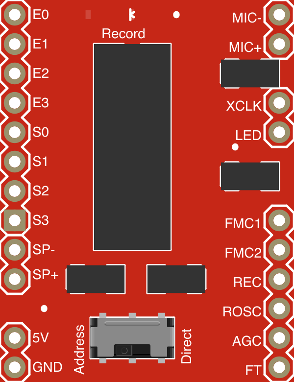
 Design with SparkFun ISD1932 Voice Recorder Breakout v1.1 in Cirkit Designer
Introduction
The SparkFun ISD1932 Voice Recorder Breakout v1.1 (Manufacturer Part ID: BOB-09579) is a compact and versatile voice recording module designed for audio recording and playback applications. It features a built-in microphone, speaker output, and configurable recording durations, making it an excellent choice for projects requiring sound playback or voice prompts. The module is based on the ISD1932 chip, which provides high-quality audio recording and playback capabilities.
Explore Projects Built with SparkFun ISD1932 Voice Recorder Breakout v1.1
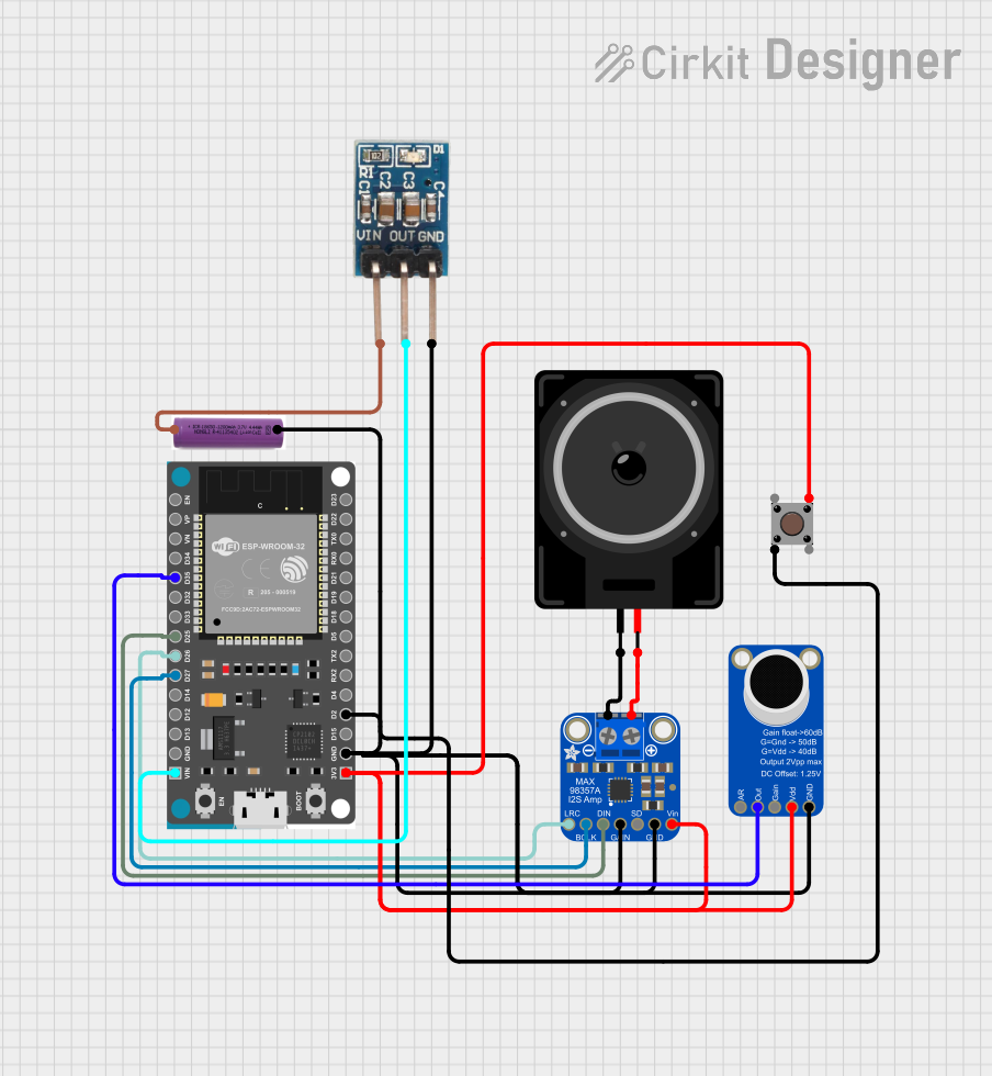 Open Project in Cirkit Designer
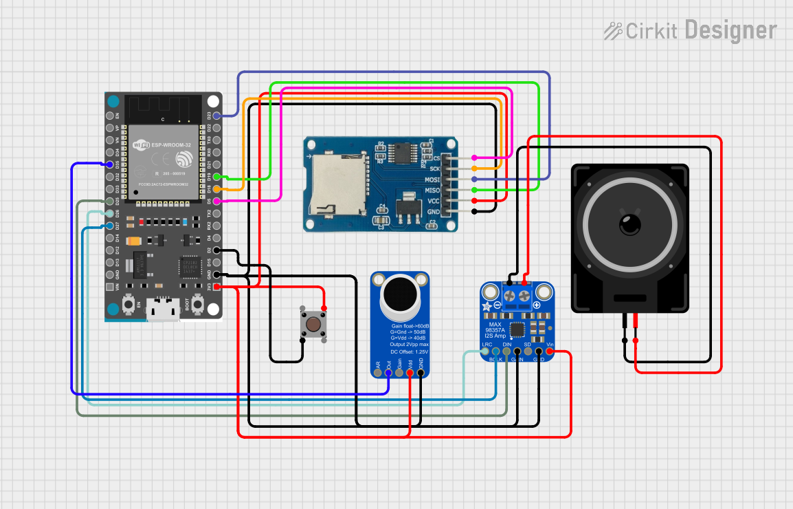 Open Project in Cirkit Designer
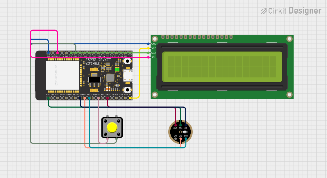 Open Project in Cirkit Designer
 Open Project in Cirkit Designer
Explore Projects Built with SparkFun ISD1932 Voice Recorder Breakout v1.1
Open Project in Cirkit DesignerOpen Project in Cirkit DesignerOpen Project in Cirkit DesignerOpen Project in Cirkit DesignerCommon Applications and Use Cases
- Interactive voice prompts for embedded systems
- Audio playback for toys and educational devices
- Voice reminders or alarms
- Sound effects for DIY projects
- Prototyping audio-enabled IoT devices
Technical Specifications
The following table outlines the key technical details of the SparkFun ISD1932 Voice Recorder Breakout v1.1:
| Parameter | Specification |
|---|---|
| Operating Voltage | 2.4V to 5.5V DC |
| Recording Duration | Configurable: 8, 10.6, or 16 seconds |
| Audio Quality | 4 kHz to 12 kHz sampling rate |
| Built-in Microphone | Yes |
| Speaker Output | 8Ω speaker support |
| External Audio Input | Supported |
| Control Interface | Push-button or microcontroller (e.g., Arduino) |
| Dimensions | 1.5" x 1.0" (38mm x 25mm) |
Pin Configuration and Descriptions
The breakout board has the following pin layout:
| Pin | Name | Description |
|---|---|---|
| 1 | VCC | Power supply input (2.4V to 5.5V DC). |
| 2 | GND | Ground connection. |
| 3 | REC | Active-low pin to start recording. |
| 4 | PLAYE | Active-low pin for edge-triggered playback. |
| 5 | PLAYL | Active-low pin for level-triggered playback. |
| 6 | FT | Feed-through mode for real-time audio monitoring. |
| 7 | MIC+ | Positive terminal for the built-in microphone. |
| 8 | MIC- | Negative terminal for the built-in microphone. |
| 9 | SP+ | Positive terminal for speaker output. |
| 10 | SP- | Negative terminal for speaker output. |
Usage Instructions
How to Use the Component in a Circuit
- Power the Module: Connect the
VCCpin to a 3.3V or 5V power source and theGNDpin to ground. - Recording Audio:
- Connect a push-button between the
RECpin andGND. - Press and hold the button to start recording. Release the button to stop recording.
- Connect a push-button between the
- Playback Audio:
- For edge-triggered playback, connect a push-button between the
PLAYEpin andGND. Press the button to play the recorded audio once. - For level-triggered playback, connect a push-button between the
PLAYLpin andGND. The audio will play as long as the button is held down.
- For edge-triggered playback, connect a push-button between the
- Speaker Connection: Connect an 8Ω speaker to the
SP+andSP-pins for audio output. - Optional Feed-Through Mode: To monitor audio in real-time, connect the
FTpin toGND.
Important Considerations and Best Practices
- Ensure the power supply voltage is within the specified range (2.4V to 5.5V) to avoid damaging the module.
- Use an 8Ω speaker for optimal audio output. Higher impedance speakers may result in lower volume.
- Avoid recording in noisy environments to achieve better audio quality.
- If using an external microcontroller (e.g., Arduino), ensure proper debounce handling for push-button inputs.
Example Arduino Code
The following example demonstrates how to control the ISD1932 module using an Arduino UNO:
// Pin definitions for the ISD1932 module
const int REC_PIN = 2;    // Pin connected to the REC pin on the module
const int PLAYE_PIN = 3;  // Pin connected to the PLAYE pin on the module

void setup() {
  // Set pin modes
  pinMode(REC_PIN, OUTPUT);
  pinMode(PLAYE_PIN, OUTPUT);

  // Initialize pins to HIGH (inactive state)
  digitalWrite(REC_PIN, HIGH);
  digitalWrite(PLAYE_PIN, HIGH);
}

void loop() {
  // Example: Record audio for 5 seconds
  digitalWrite(REC_PIN, LOW);  // Start recording
  delay(5000);                 // Record for 5 seconds
  digitalWrite(REC_PIN, HIGH); // Stop recording
  delay(2000);                 // Wait for 2 seconds

  // Example: Play the recorded audio
  digitalWrite(PLAYE_PIN, LOW);  // Trigger playback
  delay(100);                    // Short delay to ensure edge trigger
  digitalWrite(PLAYE_PIN, HIGH); // End playback trigger
  delay(5000);                   // Wait for playback to finish
}
Troubleshooting and FAQs
Common Issues and Solutions
No Audio Output:
- Ensure the speaker is properly connected to the
SP+andSP-pins. - Verify that the module is powered correctly (check
VCCandGNDconnections). - Check if the recording process was successful.
- Ensure the speaker is properly connected to the
Poor Audio Quality:
- Record in a quieter environment to reduce background noise.
- Ensure the microphone is not obstructed or damaged.
- Use the appropriate sampling rate for your application.
Playback Not Triggering:
- Confirm that the
PLAYEorPLAYLpin is correctly connected to a push-button or microcontroller. - Check for loose or faulty connections.
- Confirm that the
Module Not Responding:
- Verify that the power supply voltage is within the specified range.
- Inspect all connections for shorts or loose wires.
FAQs
Q: Can I use an external microphone with this module?
A: No, the module is designed to work with its built-in microphone. External audio input is supported via the feed-through mode.
Q: How can I extend the recording duration?
A: The recording duration is fixed and depends on the sampling rate. Lowering the sampling rate increases the duration but reduces audio quality.
Q: Can I use this module with a 3.3V microcontroller?
A: Yes, the module operates within a voltage range of 2.4V to 5.5V, making it compatible with 3.3V systems.
Q: Is it possible to store multiple recordings?
A: No, the ISD1932 chip supports only one recording at a time. New recordings overwrite the previous one.