
How to Use Lora Ra-01: Examples, Pinouts, and Specs
 Design with Lora Ra-01 in Cirkit Designer
Introduction
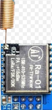
The Lora Ra-01 is a long-range, low-power wireless transceiver module designed for Internet of Things (IoT) applications. Manufactured by Lora and based on the SX1278 chipset, this module leverages LoRa (Long Range) modulation technology to enable communication over distances of several kilometers. Its low power consumption makes it particularly suitable for battery-operated devices.
Explore Projects Built with Lora Ra-01
 Open Project in Cirkit Designer
 Open Project in Cirkit Designer
 Open Project in Cirkit Designer
 Open Project in Cirkit Designer
Explore Projects Built with Lora Ra-01
Open Project in Cirkit DesignerOpen Project in Cirkit DesignerOpen Project in Cirkit DesignerOpen Project in Cirkit DesignerCommon Applications and Use Cases
- Smart agriculture (e.g., soil moisture sensors, weather stations)
- Industrial automation and monitoring
- Smart cities (e.g., parking sensors, streetlight control)
- Asset tracking and geolocation
- Home automation and security systems
- Environmental monitoring (e.g., air quality sensors)
Technical Specifications
The Lora Ra-01 module is designed to provide robust and efficient wireless communication. Below are its key technical specifications:
| Parameter | Value |
|---|---|
| Chipset | SX1278 |
| Frequency Range | 433 MHz (default) |
| Modulation | LoRa (Long Range) |
| Communication Range | Up to 10 km (line of sight) |
| Data Rate | 0.018 kbps to 37.5 kbps |
| Supply Voltage | 1.8V to 3.7V |
| Operating Current | 10.8 mA (transmit mode) |
| Sleep Current | < 200 nA |
| Output Power | Up to +20 dBm |
| Sensitivity | -148 dBm |
| Operating Temperature | -40°C to +85°C |
| Dimensions | 17 mm x 16 mm x 2.8 mm |
Pin Configuration and Descriptions
The Lora Ra-01 module has 16 pins. Below is the pinout and description:
| Pin Number | Pin Name | Description |
|---|---|---|
| 1 | GND | Ground |
| 2 | DIO0 | Digital I/O Pin 0 (Interrupt/Status Output) |
| 3 | DIO1 | Digital I/O Pin 1 |
| 4 | DIO2 | Digital I/O Pin 2 |
| 5 | DIO3 | Digital I/O Pin 3 |
| 6 | DIO4 | Digital I/O Pin 4 |
| 7 | DIO5 | Digital I/O Pin 5 |
| 8 | GND | Ground |
| 9 | MISO | SPI Master-In-Slave-Out |
| 10 | MOSI | SPI Master-Out-Slave-In |
| 11 | SCK | SPI Clock |
| 12 | NSS | SPI Chip Select |
| 13 | RESET | Reset Pin |
| 14 | 3.3V | Power Supply (3.3V) |
| 15 | ANT | Antenna Connection |
| 16 | GND | Ground |
Usage Instructions
How to Use the Lora Ra-01 in a Circuit
- Power Supply: Connect the 3.3V pin to a regulated 3.3V power source. Ensure the ground (GND) pins are connected to the circuit's ground.
- SPI Communication: Connect the SPI pins (MISO, MOSI, SCK, NSS) to the corresponding SPI pins on your microcontroller.
- Antenna: Attach a suitable 433 MHz antenna to the ANT pin for optimal performance.
- Reset: Use the RESET pin to initialize the module during startup.
- Digital I/O Pins: Use the DIO pins for interrupts or status monitoring as required by your application.
Important Considerations and Best Practices
- Power Supply: Ensure a stable 3.3V power supply. Using a higher voltage may damage the module.
- Antenna Placement: Place the antenna away from other components to minimize interference.
- SPI Configuration: Configure the SPI interface on your microcontroller to match the module's requirements (e.g., clock polarity and phase).
- Regulatory Compliance: Ensure compliance with local regulations for operating at 433 MHz.
Example: Connecting to an Arduino UNO
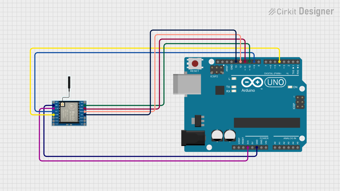
Below is an example of how to connect the Lora Ra-01 to an Arduino UNO and send data:
Wiring Diagram
| Lora Ra-01 Pin | Arduino UNO Pin |
|---|---|
| 3.3V | 3.3V |
| GND | GND |
| MISO | Pin 12 |
| MOSI | Pin 11 |
| SCK | Pin 13 |
| NSS | Pin 10 |
| RESET | Pin 9 |
Arduino Code Example
#include <SPI.h>
#include <LoRa.h> // Include the LoRa library

#define NSS 10    // Chip Select pin
#define RESET 9   // Reset pin
#define DIO0 2    // DIO0 pin

void setup() {
  Serial.begin(9600); // Initialize serial communication
  while (!Serial);

  Serial.println("Initializing LoRa module...");

  // Initialize LoRa module
  LoRa.setPins(NSS, RESET, DIO0);
  if (!LoRa.begin(433E6)) { // Set frequency to 433 MHz
    Serial.println("LoRa initialization failed!");
    while (1);
  }

  Serial.println("LoRa initialized successfully!");
}

void loop() {
  Serial.println("Sending packet...");
  LoRa.beginPacket();          // Start a new packet
  LoRa.print("Hello, LoRa!");  // Add data to the packet
  LoRa.endPacket();            // Send the packet

  delay(5000); // Wait 5 seconds before sending the next packet
}
Troubleshooting and FAQs
Common Issues and Solutions
Module Not Responding
- Cause: Incorrect wiring or power supply.
- Solution: Double-check all connections and ensure a stable 3.3V power supply.
Poor Communication Range
- Cause: Improper antenna placement or interference.
- Solution: Use a high-quality antenna and place it away from other components.
LoRa Initialization Fails
- Cause: Incorrect SPI configuration or frequency mismatch.
- Solution: Verify SPI connections and ensure the frequency is set to 433 MHz.
High Power Consumption
- Cause: Module not entering sleep mode.
- Solution: Use the appropriate library functions to enable sleep mode when idle.
FAQs
Can the Lora Ra-01 operate at frequencies other than 433 MHz?
- No, the Lora Ra-01 is specifically designed for 433 MHz operation.
What is the maximum communication range?
- The module can achieve up to 10 km in line-of-sight conditions. Obstacles and interference may reduce this range.
Is the Lora Ra-01 compatible with other LoRa modules?
- Yes, as long as the other modules operate on the same frequency and use the LoRa protocol.
Can I use the Lora Ra-01 with a 5V microcontroller?
- Yes, but you must use a level shifter to convert the 5V logic to 3.3V to avoid damaging the module.