Cirkit Designer Logo
Cirkit Designer
Your all-in-one circuit design IDE
Home / 
Component Documentation

How to Use KY-032 Infrared Obstacle Avoidance Sensor Module: Examples, Pinouts, and Specs

Image of KY-032 Infrared Obstacle Avoidance Sensor Module
Cirkit Designer LogoDesign with KY-032 Infrared Obstacle Avoidance Sensor Module in Cirkit Designer

Introduction

The KY-032 Infrared Obstacle Avoidance Sensor Module is an electronic device that utilizes infrared technology to detect the presence of obstacles in its proximity. It is widely used in robotics, automated vehicles, and various DIY projects for navigation and collision avoidance purposes. The sensor operates by emitting an infrared signal and then detecting the reflection of this signal off an object in its path.

Explore Projects Built with KY-032 Infrared Obstacle Avoidance Sensor Module

Use Cirkit Designer to design, explore, and prototype these projects online. Some projects support real-time simulation. Click "Open Project" to start designing instantly!
MakerEdu Creator with Bluetooth, IR Sensors, LCD Display, and Push Button Interaction
Image of MKL Distance Measurement: A project utilizing KY-032 Infrared Obstacle Avoidance Sensor Module in a practical application
This circuit features a MakerEdu Creator microcontroller board interfaced with two MKE-S11 IR Infrared Obstacle Avoidance Sensors, a MKE-M02 Push Button Tact Switch, a MKE-M15 Bluetooth module, and a MKE-M08 LCD2004 I2C display module. The push button is connected to a digital input for user interaction, while the IR sensors are likely used for detecting obstacles. The Bluetooth module enables wireless communication, and the LCD display provides a user interface for displaying information or statuses.
Cirkit Designer LogoOpen Project in Cirkit Designer
Arduino-Based Obstacle Avoiding and Line Following Robot with IR and Ultrasonic Sensors
Image of FYP Prototype: A project utilizing KY-032 Infrared Obstacle Avoidance Sensor Module in a practical application
This circuit is a robotic system that uses an Arduino UNO and various sensors, including infrared, ultrasonic, and obstacle avoidance sensors, to detect and navigate its environment. It controls multiple motors through an L298N motor driver and includes a servo motor for additional movement capabilities. The system is powered by a 18650 Li-Ion battery and features an LED indicator.
Cirkit Designer LogoOpen Project in Cirkit Designer
Arduino Nano and ESP32-Based Smart Environmental Monitoring System with Battery Power
Image of 19301 schematic: A project utilizing KY-032 Infrared Obstacle Avoidance Sensor Module in a practical application
This circuit is a multi-sensor monitoring system using an Arduino Nano and an ESP32. It includes sensors for obstacle detection (IR sensors), air quality (MQ135), and temperature/humidity (DHT11), with visual indicators (LEDs) and an auditory alert (buzzer). The system is powered by a 18650 Li-ion battery pack regulated by a 7805 voltage regulator.
Cirkit Designer LogoOpen Project in Cirkit Designer
Arduino UNO-Based Sensor Monitoring and GSM Communication System
Image of pot new: A project utilizing KY-032 Infrared Obstacle Avoidance Sensor Module in a practical application
This is a multifunctional Arduino-based system designed to interface with an ultrasonic sensor for distance measurement, an IR sensor for object detection, a GPS module for location tracking, a GSM module for cellular communication, an I2C LCD display for user interface, and an OV7670 camera module for image capture. The Arduino manages sensor data processing and module communication, indicating a complex application such as a security or surveillance device with remote reporting capabilities.
Cirkit Designer LogoOpen Project in Cirkit Designer

Explore Projects Built with KY-032 Infrared Obstacle Avoidance Sensor Module

Use Cirkit Designer to design, explore, and prototype these projects online. Some projects support real-time simulation. Click "Open Project" to start designing instantly!
Image of MKL Distance Measurement: A project utilizing KY-032 Infrared Obstacle Avoidance Sensor Module in a practical application
MakerEdu Creator with Bluetooth, IR Sensors, LCD Display, and Push Button Interaction
This circuit features a MakerEdu Creator microcontroller board interfaced with two MKE-S11 IR Infrared Obstacle Avoidance Sensors, a MKE-M02 Push Button Tact Switch, a MKE-M15 Bluetooth module, and a MKE-M08 LCD2004 I2C display module. The push button is connected to a digital input for user interaction, while the IR sensors are likely used for detecting obstacles. The Bluetooth module enables wireless communication, and the LCD display provides a user interface for displaying information or statuses.
Cirkit Designer LogoOpen Project in Cirkit Designer
Image of FYP Prototype: A project utilizing KY-032 Infrared Obstacle Avoidance Sensor Module in a practical application
Arduino-Based Obstacle Avoiding and Line Following Robot with IR and Ultrasonic Sensors
This circuit is a robotic system that uses an Arduino UNO and various sensors, including infrared, ultrasonic, and obstacle avoidance sensors, to detect and navigate its environment. It controls multiple motors through an L298N motor driver and includes a servo motor for additional movement capabilities. The system is powered by a 18650 Li-Ion battery and features an LED indicator.
Cirkit Designer LogoOpen Project in Cirkit Designer
Image of 19301 schematic: A project utilizing KY-032 Infrared Obstacle Avoidance Sensor Module in a practical application
Arduino Nano and ESP32-Based Smart Environmental Monitoring System with Battery Power
This circuit is a multi-sensor monitoring system using an Arduino Nano and an ESP32. It includes sensors for obstacle detection (IR sensors), air quality (MQ135), and temperature/humidity (DHT11), with visual indicators (LEDs) and an auditory alert (buzzer). The system is powered by a 18650 Li-ion battery pack regulated by a 7805 voltage regulator.
Cirkit Designer LogoOpen Project in Cirkit Designer
Image of pot new: A project utilizing KY-032 Infrared Obstacle Avoidance Sensor Module in a practical application
Arduino UNO-Based Sensor Monitoring and GSM Communication System
This is a multifunctional Arduino-based system designed to interface with an ultrasonic sensor for distance measurement, an IR sensor for object detection, a GPS module for location tracking, a GSM module for cellular communication, an I2C LCD display for user interface, and an OV7670 camera module for image capture. The Arduino manages sensor data processing and module communication, indicating a complex application such as a security or surveillance device with remote reporting capabilities.
Cirkit Designer LogoOpen Project in Cirkit Designer

Common Applications and Use Cases

  • Robotics: Obstacle detection and avoidance
  • Automated guided vehicles (AGVs): Path navigation
  • Interactive installations: Movement or presence detection
  • Home automation: Security and monitoring systems

Technical Specifications

Key Technical Details

  • Operating Voltage: 3.3V to 5V DC
  • Current Consumption: 20mA
  • Detection Distance: 2cm to 40cm (adjustable)
  • Sensor Angle: 35°
  • Output Type: Digital signal (0V or 5V)

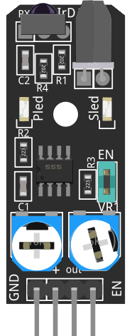
Pin Configuration and Descriptions

Pin Description
VCC Connect to 3.3V-5V power supply
GND Connect to ground
OUT Digital output signal (connect to microcontroller I/O pin)
EN Enable pin (optional use to enable/disable the sensor)

Usage Instructions

How to Use the Component in a Circuit

  1. Connect the VCC pin to a 3.3V-5V power supply.
  2. Connect the GND pin to the ground of the power supply.
  3. Connect the OUT pin to a digital input pin on a microcontroller, such as an Arduino.
  4. (Optional) Connect the EN pin to a digital output pin on the microcontroller if you wish to control the enabling of the sensor programmatically.

Important Considerations and Best Practices

  • Ensure that the sensor is mounted securely and that its path is unobstructed for accurate detection.
  • Adjust the onboard potentiometer to calibrate the detection distance as per your requirements.
  • Avoid exposing the sensor to direct sunlight or other strong infrared sources to prevent false detections.
  • Use pull-up or pull-down resistors on the OUT pin if required by your microcontroller's input pin specifications.

Example Code for Arduino UNO

// Define the KY-032 sensor output pin
const int obstacleSensorPin = 2;

void setup() {
  pinMode(obstacleSensorPin, INPUT); // Set the sensor pin as input
  Serial.begin(9600);                // Start serial communication
}

void loop() {
  int sensorValue = digitalRead(obstacleSensorPin); // Read the sensor value
  if (sensorValue == LOW) {                         // Check if an obstacle is detected
    Serial.println("Obstacle detected!");
  } else {
    Serial.println("Path is clear.");
  }
  delay(200); // Short delay before next reading
}

Troubleshooting and FAQs

Common Issues Users Might Face

  • Inconsistent Detection: If the sensor is giving inconsistent results, try adjusting the potentiometer to calibrate the detection distance.
  • No Output Signal: Ensure that the power supply is connected correctly and that the voltage levels are within the specified range. Also, check the connections to the microcontroller.

Solutions and Tips for Troubleshooting

  • Calibration: Use a small screwdriver to adjust the onboard potentiometer until the desired detection range is achieved.
  • Wiring Check: Double-check all connections, especially the VCC and GND pins, to ensure they are secure and correctly wired.
  • Avoid Interference: Keep the sensor away from other infrared-emitting sources to prevent interference.

FAQs

Q: Can the sensor detect all types of materials? A: The sensor is most effective with objects that reflect infrared well. Some materials, especially those that are shiny or transparent, may not be detected as reliably.

Q: How can I extend the detection range of the sensor? A: The detection range can be adjusted using the onboard potentiometer. However, the maximum effective range is about 40cm.

Q: Is it possible to use multiple KY-032 sensors together? A: Yes, you can use multiple sensors in a project. Ensure that each sensor's output pin is connected to a separate digital input pin on the microcontroller.

Q: What should I do if the sensor is always indicating an obstacle, even when there is none? A: This could be due to interference from other infrared sources or incorrect calibration. Adjust the potentiometer and ensure the sensor is not facing any strong infrared-emitting sources.