How to Use Second Order Systems: Examples, Pinouts, and Specs
Introduction
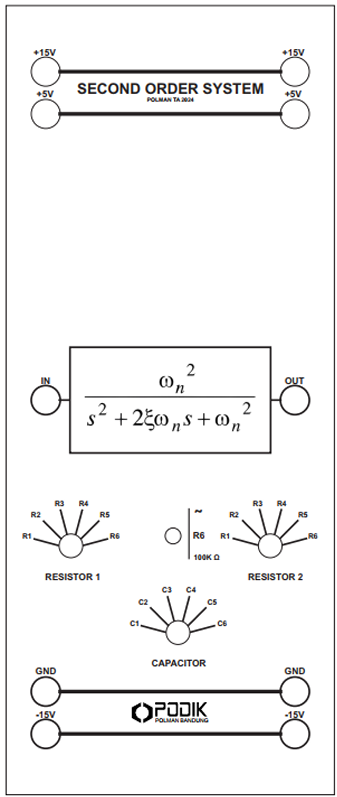
A Second Order System is a dynamic system characterized by a second-order differential equation. Manufactured by PODIK, this system is widely used in control theory and signal processing to model systems with two energy storage elements, such as mass-spring-damper systems or RLC circuits. The system's behavior is primarily defined by its natural frequency and damping ratio, which determine its response to various inputs.
Explore Projects Built with Second Order Systems
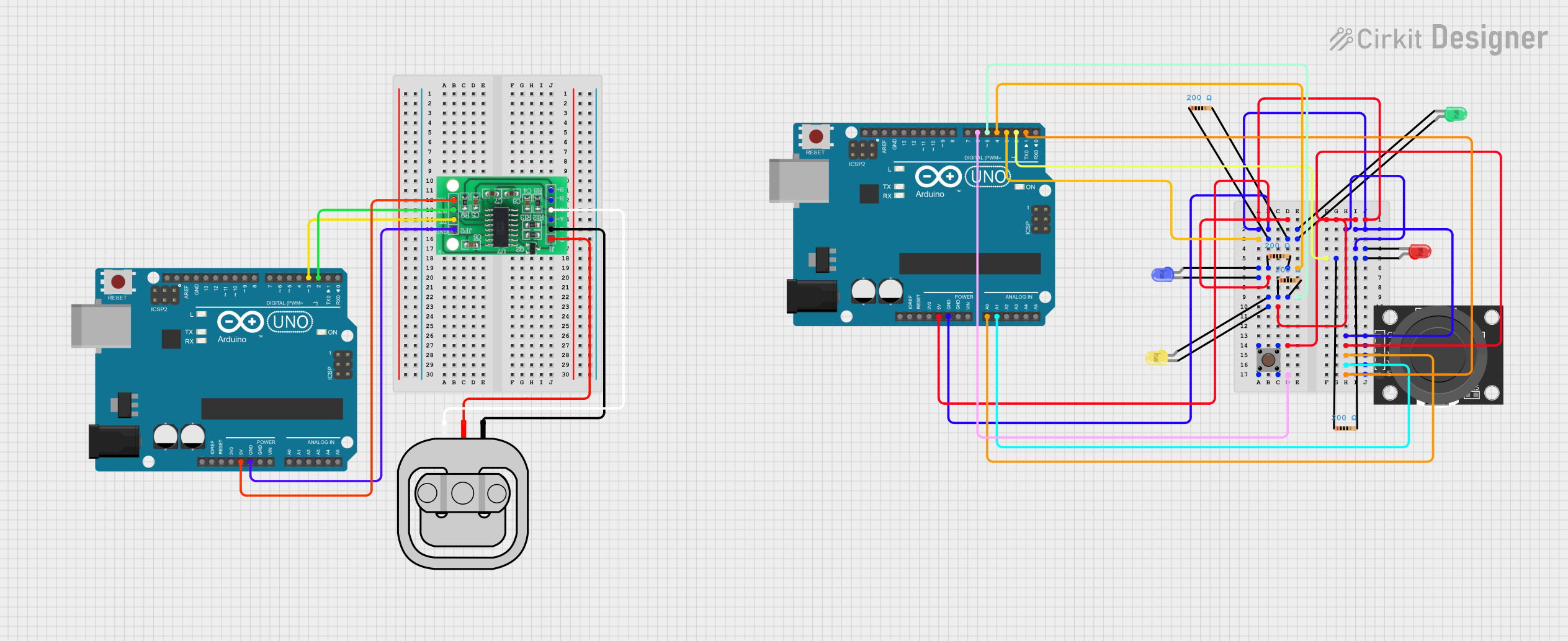
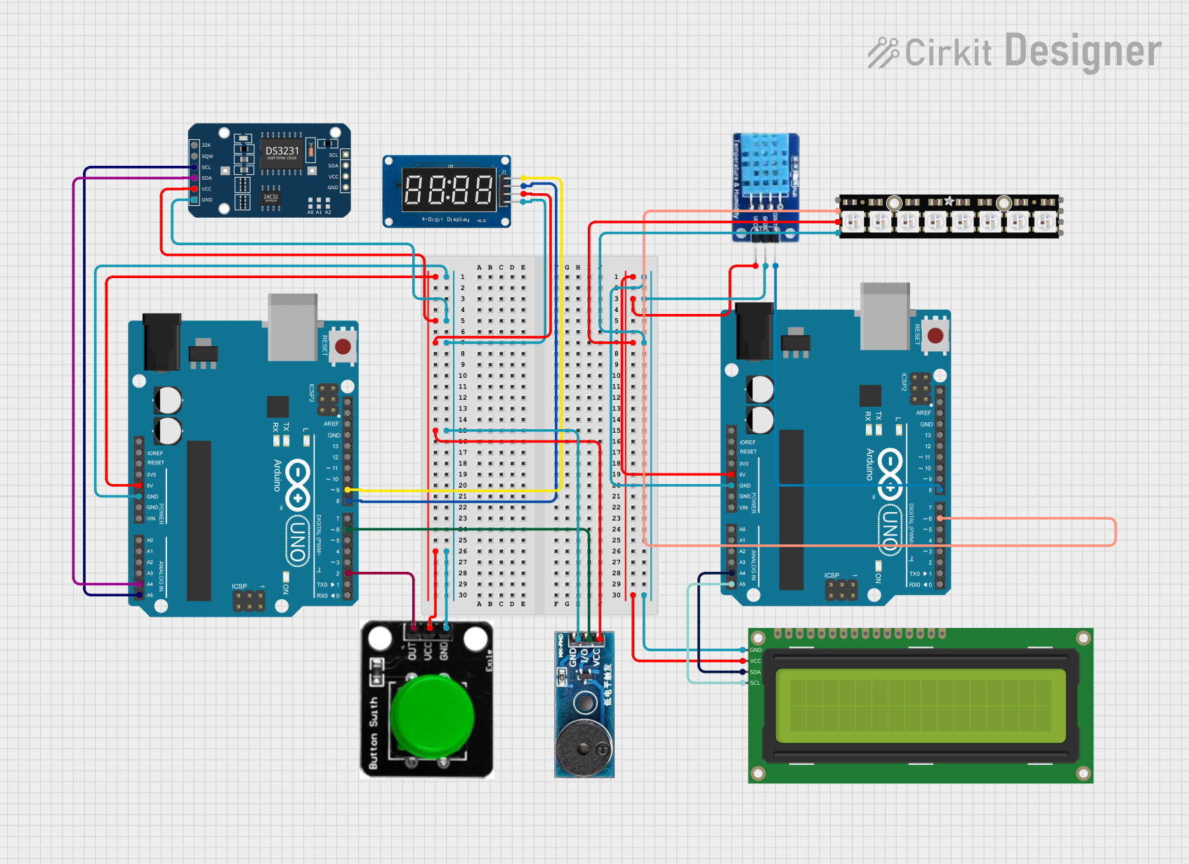
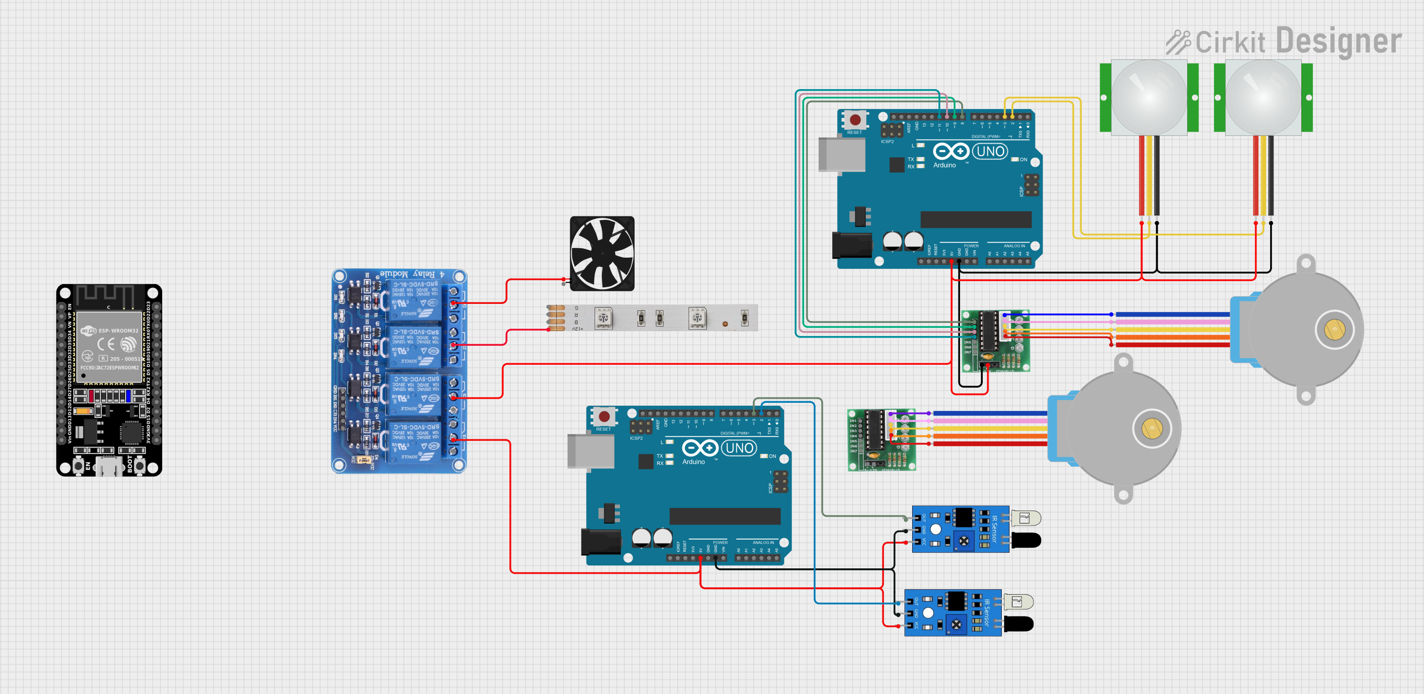
Explore Projects Built with Second Order Systems
Common Applications and Use Cases
- Control Systems: Used in PID controllers and feedback systems.
- Signal Processing: Filters, oscillators, and resonance circuits.
- Mechanical Systems: Modeling mass-spring-damper systems.
- Electrical Systems: RLC circuits and power system stability analysis.
Technical Specifications
The following table outlines the key technical parameters of the PODIK Second Order System:
| Parameter | Description |
|---|---|
| Natural Frequency (ωn) | The frequency at which the system oscillates in the absence of damping (rad/s). |
| Damping Ratio (ζ) | A dimensionless measure of damping in the system. |
| System Type | Linear, time-invariant, second-order dynamic system. |
| Input | Step, impulse, or sinusoidal signals. |
| Output | System response (e.g., displacement, voltage, or current). |
Pin Configuration and Descriptions
The PODIK Second Order System is typically implemented in circuits or software simulations. Below is a general pin configuration for hardware implementations:
| Pin | Name | Description |
|---|---|---|
| 1 | Input Signal | Accepts the input signal (e.g., step, impulse, or sinusoidal). |
| 2 | Ground (GND) | Connects to the system ground. |
| 3 | Output Signal | Provides the system's response to the input signal. |
| 4 | Control Input | Optional pin for adjusting system parameters like damping ratio or frequency. |
Usage Instructions
How to Use the Component in a Circuit
- Connect the Input Signal: Apply the desired input signal (e.g., step or sinusoidal) to the Input Signal pin.
- Ground the System: Ensure the Ground (GND) pin is connected to the circuit's ground.
- Monitor the Output: Measure the system's response at the Output Signal pin using an oscilloscope or data acquisition system.
- Adjust Parameters: If applicable, use the Control Input pin to modify system parameters like damping ratio or natural frequency.
Important Considerations and Best Practices
- Stability: Ensure the damping ratio (ζ) is appropriate for the application. Overdamped systems (ζ > 1) may respond too slowly, while underdamped systems (ζ < 1) may oscillate excessively.
- Frequency Response: For sinusoidal inputs, ensure the input frequency does not exceed the system's natural frequency (ωn).
- Power Supply: Verify that the system's power requirements are met to avoid malfunction or damage.
- Simulation: For software-based implementations, use tools like MATLAB, Simulink, or Python libraries (e.g., SciPy) to model and analyze the system.
Example: Arduino UNO Integration
The PODIK Second Order System can be simulated or controlled using an Arduino UNO. Below is an example code snippet to generate a step input and observe the system's response:
// Arduino code to generate a step input for a second order system
const int inputPin = 9;  // Pin connected to the system's Input Signal
const int outputPin = A0; // Pin to read the system's Output Signal

void setup() {
  pinMode(inputPin, OUTPUT);  // Set inputPin as output
  pinMode(outputPin, INPUT);  // Set outputPin as input
  Serial.begin(9600);         // Initialize serial communication
}

void loop() {
  // Generate a step input signal
  digitalWrite(inputPin, HIGH);  // Apply step input
  delay(1000);                   // Wait for 1 second
  digitalWrite(inputPin, LOW);   // Remove step input
  delay(1000);                   // Wait for 1 second

  // Read and print the system's output
  int outputValue = analogRead(outputPin);  // Read analog output
  Serial.print("System Output: ");
  Serial.println(outputValue);  // Print the output value to the Serial Monitor
}
Note: Ensure proper scaling and interfacing between the Arduino and the PODIK Second Order System to avoid damage.
Troubleshooting and FAQs
Common Issues and Solutions
No Output Signal:
- Cause: Input signal not applied or incorrect connections.
- Solution: Verify the input signal and ensure all connections are secure.
Excessive Oscillations:
- Cause: Damping ratio (ζ) is too low.
- Solution: Increase the damping ratio by adjusting the system parameters.
Slow Response:
- Cause: Overdamped system (ζ > 1).
- Solution: Decrease the damping ratio to achieve a faster response.
Incorrect Frequency Response:
- Cause: Input frequency exceeds the natural frequency (ωn).
- Solution: Limit the input frequency to below the system's natural frequency.
FAQs
Q: Can the PODIK Second Order System handle non-linear inputs?
A: No, the system is designed for linear inputs. Non-linear inputs may lead to unpredictable behavior.Q: How do I calculate the natural frequency and damping ratio?
A: Use the system's transfer function or differential equation to derive these parameters.Q: Can I simulate this system in software?
A: Yes, tools like MATLAB, Simulink, or Python libraries (e.g., SciPy) are ideal for simulating second order systems.
By following this documentation, users can effectively implement and troubleshoot the PODIK Second Order System in various applications.