How to Use RoboClaw 2x30A Motor Controller: Examples, Pinouts, and Specs
Introduction
The RoboClaw 2x30A Motor Controller is a dual-channel motor controller designed to drive two brushed DC motors with a maximum continuous current of 30A per channel. It offers advanced control features, including speed, direction, and position control, as well as support for multiple communication protocols such as USB, TTL serial, RC, and analog inputs. This versatile controller is ideal for robotics, automation systems, and other applications requiring precise motor control.
Explore Projects Built with RoboClaw 2x30A Motor Controller


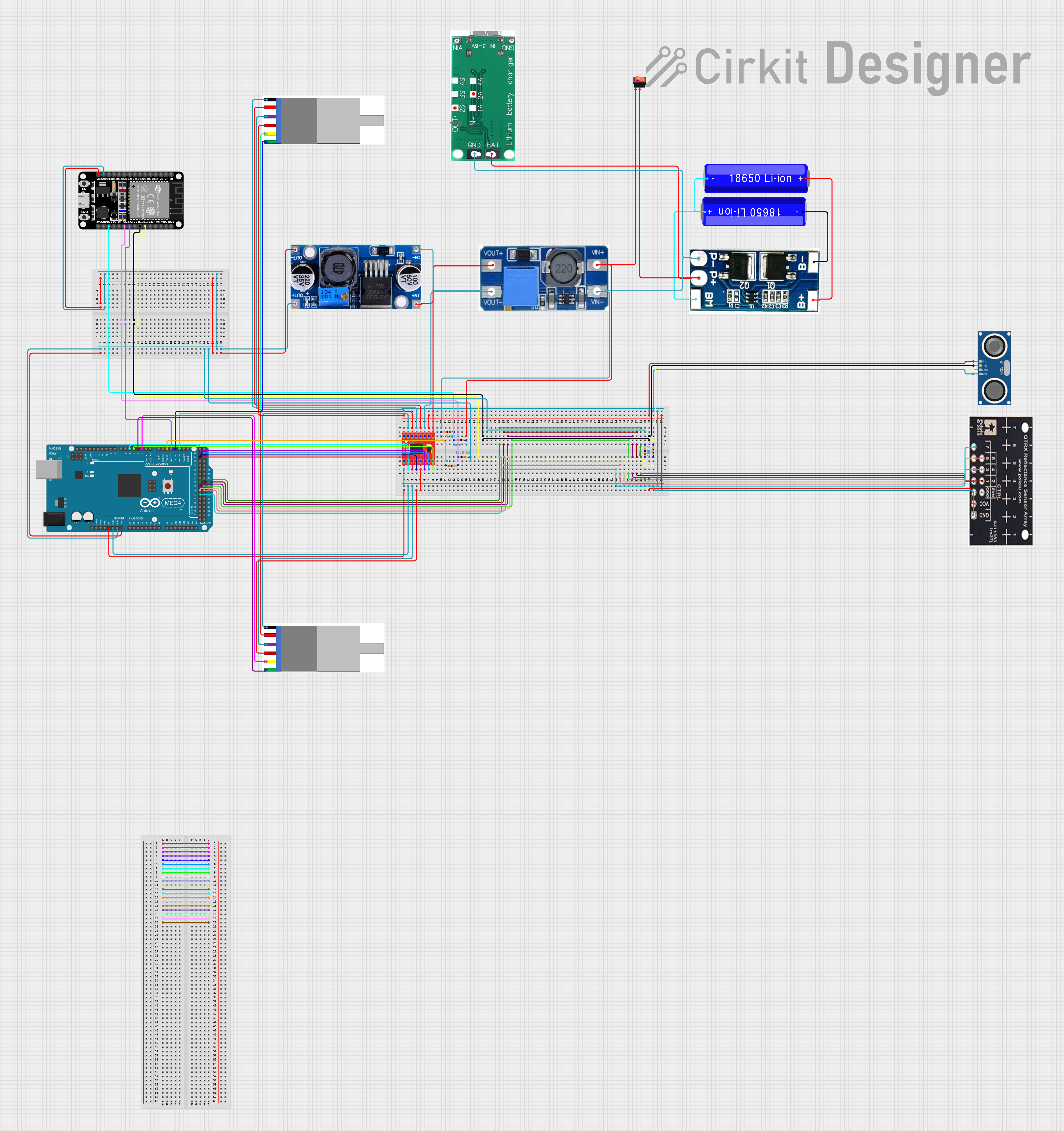
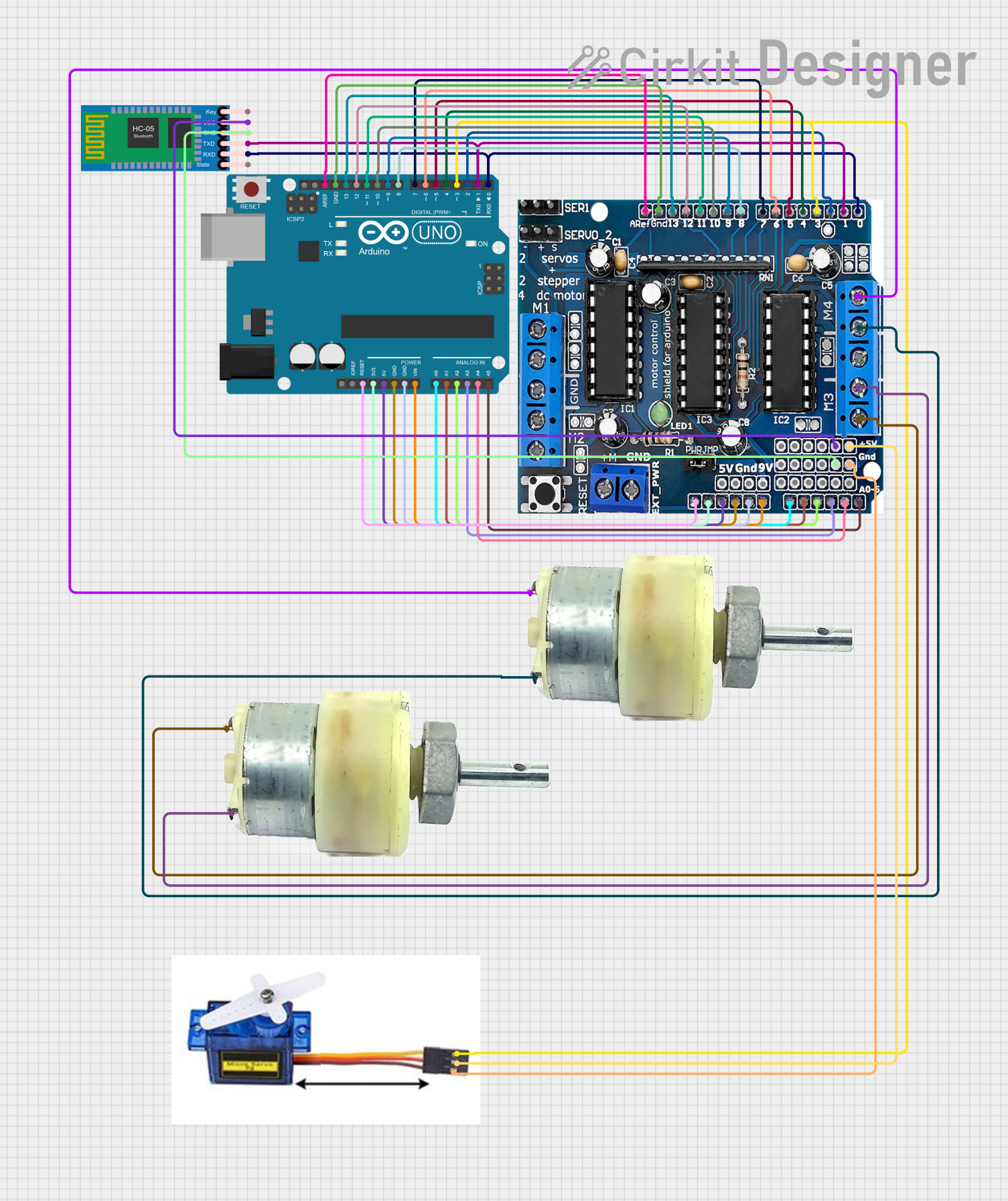
Explore Projects Built with RoboClaw 2x30A Motor Controller
Common Applications and Use Cases
- Robotics platforms (e.g., mobile robots, robotic arms)
- Automated guided vehicles (AGVs)
- Conveyor belt systems
- Remote-controlled vehicles
- Industrial automation requiring precise motor control
Technical Specifications
Key Technical Details
| Specification | Value |
|---|---|
| Motor Channels | 2 |
| Maximum Continuous Current | 30A per channel |
| Peak Current | 60A per channel (for short bursts) |
| Operating Voltage Range | 6V to 34V |
| Communication Protocols | USB, TTL Serial, RC, Analog |
| Encoder Support | Quadrature encoders (up to 19-bit) |
| Control Modes | Speed, direction, position |
| Dimensions | 3.2" x 2.4" x 1.2" (81 x 61 x 30 mm) |
| Weight | 113g |
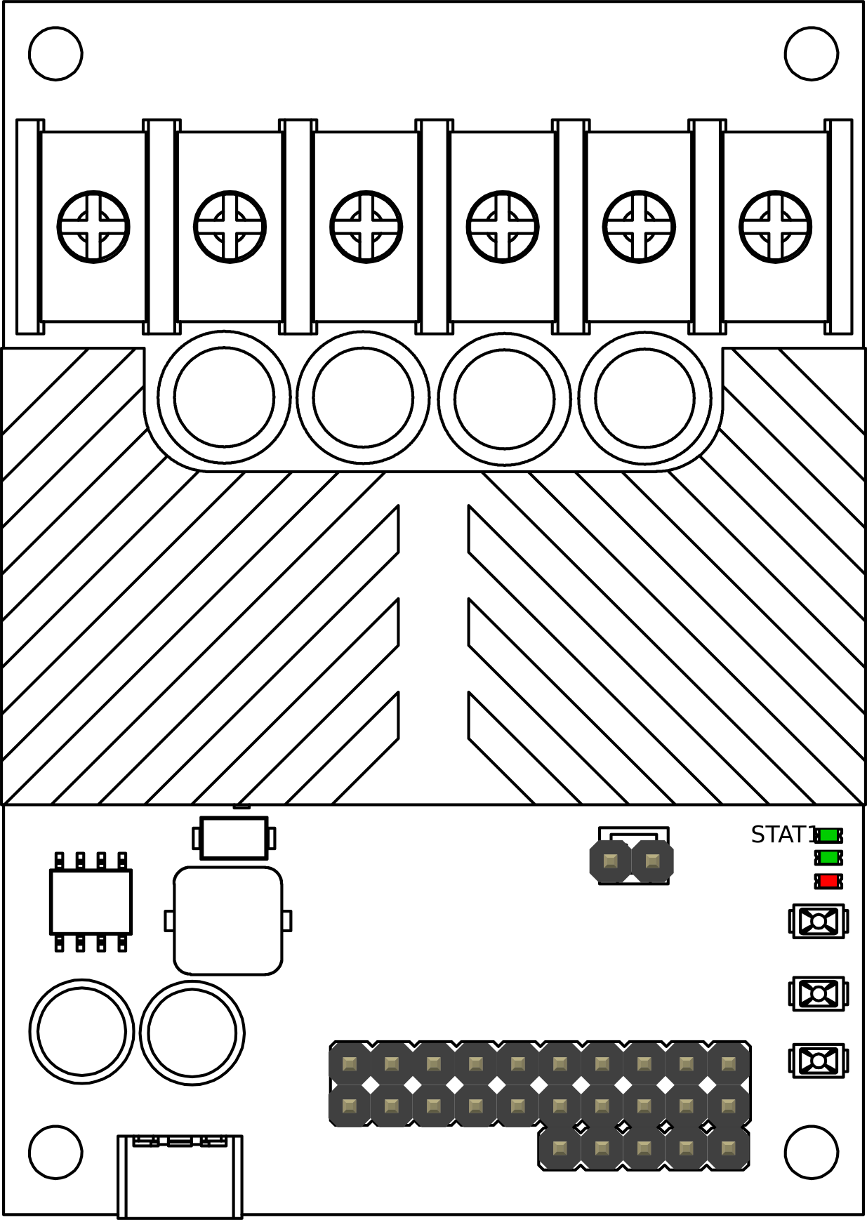
Pin Configuration and Descriptions
Power and Motor Connections
| Pin Name | Description |
|---|---|
| VMOT+ | Positive motor power input (6V to 34V) |
| VMOT- | Ground for motor power input |
| M1A, M1B | Motor 1 output terminals |
| M2A, M2B | Motor 2 output terminals |
Control and Communication Pins
| Pin Name | Description |
|---|---|
| S1, S2 | RC signal inputs for motor control |
| A1, A2 | Analog inputs for motor control |
| TX, RX | TTL serial communication pins |
| USB | USB port for communication and configuration |
| ENC1A, ENC1B | Encoder inputs for Motor 1 |
| ENC2A, ENC2B | Encoder inputs for Motor 2 |
| GND | Ground for logic and control signals |
Usage Instructions
How to Use the RoboClaw 2x30A in a Circuit
- Power Connection: Connect a power supply (6V to 34V) to the VMOT+ and VMOT- terminals. Ensure the power supply can handle the current requirements of your motors.
- Motor Connection: Connect the two DC motors to the M1A/M1B and M2A/M2B terminals.
- Control Signal: Choose a control method (e.g., USB, TTL serial, RC, or analog) and connect the appropriate pins.
- Encoder Setup (Optional): If using encoders for closed-loop control, connect the encoder outputs to the ENC1A/ENC1B and ENC2A/ENC2B pins.
- Configuration: Use the provided software or commands to configure the motor controller for your specific application.
Important Considerations and Best Practices
- Heat Dissipation: The RoboClaw 2x30A can generate heat during operation. Ensure adequate ventilation or use a heatsink if operating near the maximum current.
- Power Supply: Use a power supply with sufficient current capacity to avoid voltage drops or damage to the controller.
- Wiring: Use appropriately rated wires for motor and power connections to handle high currents.
- Safety: Always test the system with low power settings before full operation to ensure proper wiring and configuration.
Example: Using RoboClaw with Arduino UNO
Below is an example of controlling the RoboClaw 2x30A using an Arduino UNO via TTL serial communication.
#include <SoftwareSerial.h>

// Define pins for software serial communication
#define ROBOCLAW_RX 10  // Arduino pin connected to RoboClaw TX
#define ROBOCLAW_TX 11  // Arduino pin connected to RoboClaw RX

// Create a SoftwareSerial object
SoftwareSerial roboclaw(ROBOCLAW_RX, ROBOCLAW_TX);

void setup() {
  // Initialize serial communication with RoboClaw
  roboclaw.begin(38400); // Default baud rate for RoboClaw
  Serial.begin(9600);    // For debugging with the Serial Monitor

  // Send a command to stop both motors
  sendCommand(0x00, 0); // Command 0x00 stops the motors
}

void loop() {
  // Example: Set Motor 1 to 50% forward speed
  sendCommand(0x01, 64); // Command 0x01 sets Motor 1 speed (0-127)

  delay(2000); // Run motor for 2 seconds

  // Stop Motor 1
  sendCommand(0x00, 0); // Stop command
  delay(2000); // Wait for 2 seconds
}

// Function to send a command to RoboClaw
void sendCommand(uint8_t command, uint8_t value) {
  roboclaw.write(command); // Send command byte
  roboclaw.write(value);   // Send value byte
  Serial.print("Command Sent: ");
  Serial.print(command);
  Serial.print(", Value: ");
  Serial.println(value);
}
Troubleshooting and FAQs
Common Issues and Solutions
Motors Not Responding:
- Cause: Incorrect wiring or configuration.
- Solution: Double-check motor and power connections. Verify the control method and ensure the correct pins are used.
Overheating:
- Cause: Operating near maximum current without proper cooling.
- Solution: Add a heatsink or improve ventilation around the controller.
Communication Failure:
- Cause: Incorrect baud rate or wiring for communication.
- Solution: Verify the baud rate and ensure TX/RX pins are correctly connected.
Erratic Motor Behavior:
- Cause: Noise or interference in control signals.
- Solution: Use shielded cables for signal lines and ensure proper grounding.
FAQs
Q: Can I use the RoboClaw 2x30A with a 24V battery?
- A: Yes, the RoboClaw supports voltages up to 34V. Ensure your motors are rated for 24V operation.
Q: How do I update the firmware?
- A: Use the official RoboClaw software via the USB connection to update the firmware.
Q: Can I control the RoboClaw with a Raspberry Pi?
- A: Yes, the RoboClaw supports TTL serial communication, which can be used with a Raspberry Pi's UART pins.
Q: What happens if the current exceeds 30A?
- A: The RoboClaw has built-in overcurrent protection. It will limit the current or shut down to prevent damage.