Cirkit Designer Logo
Cirkit Designer
Your all-in-one circuit design IDE
Home / 
Component Documentation

How to Use line tracking: Examples, Pinouts, and Specs

Image of line tracking
Cirkit Designer LogoDesign with line tracking in Cirkit Designer

Introduction

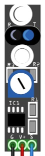
The Line Tracking Sensor (Manufacturer: Arduinno, Part ID: UNO) is a compact and efficient module designed for robotics applications. It enables robots to detect and follow a line or path, typically using infrared (IR) or optical sensors to distinguish between the line and the surrounding surface. This sensor is widely used in autonomous vehicles, line-following robots, and industrial automation systems.

Explore Projects Built with line tracking

Use Cirkit Designer to design, explore, and prototype these projects online. Some projects support real-time simulation. Click "Open Project" to start designing instantly!
Arduino UNO Line Following Robot with L298N Motor Driver and KY-033 Sensors
Image of human following robot : A project utilizing line tracking in a practical application
This circuit is a line-following robot controlled by an Arduino UNO. It uses three KY-033 line tracking sensors to detect the path and an L298N motor driver to control two DC motors, powered by a 12V battery. The Arduino processes sensor inputs to adjust motor speeds and directions, enabling the robot to follow a line.
Cirkit Designer LogoOpen Project in Cirkit Designer
Arduino-Controlled Line Following Trolley with Ultrasonic Obstacle Detection and Bluetooth Connectivity
Image of Trolly: A project utilizing line tracking in a practical application
This circuit is designed for a line-following trolley that can also avoid obstacles. It uses an Arduino UNO to control two DC motors via an L298N motor driver, receives distance data from an HC-SR04 ultrasonic sensor, and line detection input from a TCRT 5000 IR sensor. Additionally, it includes an HC-05 Bluetooth module for potential wireless communication.
Cirkit Designer LogoOpen Project in Cirkit Designer
ESP32-Controlled Dual Ultrasonic Sensor and Line Tracking Robot
Image of Gilbert Project: A project utilizing line tracking in a practical application
This circuit is designed for a robotic vehicle featuring obstacle detection and line tracking capabilities. It uses an ESP32 microcontroller to process signals from ultrasonic and line tracking sensors and to control motor drivers for vehicle propulsion. The system is powered by a lipo battery, and the ESP32 manages sensor inputs and motor outputs to navigate the vehicle autonomously.
Cirkit Designer LogoOpen Project in Cirkit Designer
Arduino UNO Line Following Robot with Dual Motor Control
Image of CFL_3Sensor_byPu: A project utilizing line tracking in a practical application
This circuit is a line-following robot controlled by an Arduino UNO. It uses a 3-channel line tracking sensor to detect the path and an L298N motor driver to control two DC motors for movement. The robot's behavior is programmed to move forward, turn left, or turn right based on the sensor inputs.
Cirkit Designer LogoOpen Project in Cirkit Designer

Explore Projects Built with line tracking

Use Cirkit Designer to design, explore, and prototype these projects online. Some projects support real-time simulation. Click "Open Project" to start designing instantly!
Image of human following robot : A project utilizing line tracking in a practical application
Arduino UNO Line Following Robot with L298N Motor Driver and KY-033 Sensors
This circuit is a line-following robot controlled by an Arduino UNO. It uses three KY-033 line tracking sensors to detect the path and an L298N motor driver to control two DC motors, powered by a 12V battery. The Arduino processes sensor inputs to adjust motor speeds and directions, enabling the robot to follow a line.
Cirkit Designer LogoOpen Project in Cirkit Designer
Image of Trolly: A project utilizing line tracking in a practical application
Arduino-Controlled Line Following Trolley with Ultrasonic Obstacle Detection and Bluetooth Connectivity
This circuit is designed for a line-following trolley that can also avoid obstacles. It uses an Arduino UNO to control two DC motors via an L298N motor driver, receives distance data from an HC-SR04 ultrasonic sensor, and line detection input from a TCRT 5000 IR sensor. Additionally, it includes an HC-05 Bluetooth module for potential wireless communication.
Cirkit Designer LogoOpen Project in Cirkit Designer
Image of Gilbert Project: A project utilizing line tracking in a practical application
ESP32-Controlled Dual Ultrasonic Sensor and Line Tracking Robot
This circuit is designed for a robotic vehicle featuring obstacle detection and line tracking capabilities. It uses an ESP32 microcontroller to process signals from ultrasonic and line tracking sensors and to control motor drivers for vehicle propulsion. The system is powered by a lipo battery, and the ESP32 manages sensor inputs and motor outputs to navigate the vehicle autonomously.
Cirkit Designer LogoOpen Project in Cirkit Designer
Image of CFL_3Sensor_byPu: A project utilizing line tracking in a practical application
Arduino UNO Line Following Robot with Dual Motor Control
This circuit is a line-following robot controlled by an Arduino UNO. It uses a 3-channel line tracking sensor to detect the path and an L298N motor driver to control two DC motors for movement. The robot's behavior is programmed to move forward, turn left, or turn right based on the sensor inputs.
Cirkit Designer LogoOpen Project in Cirkit Designer

Common Applications and Use Cases

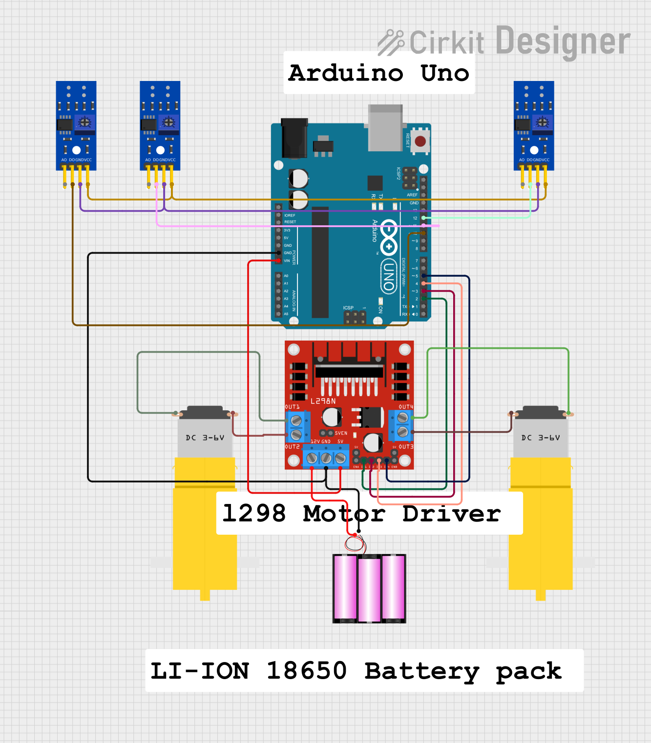
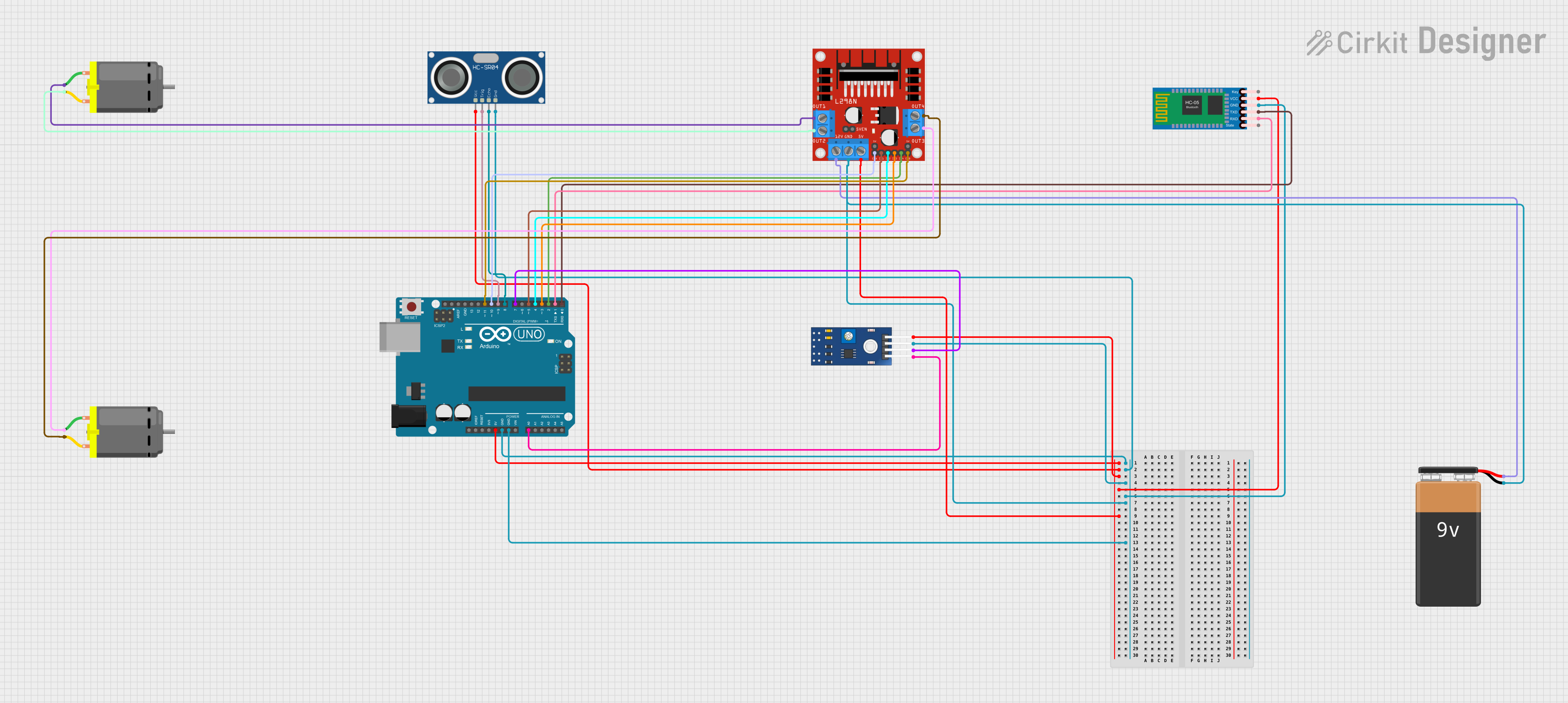
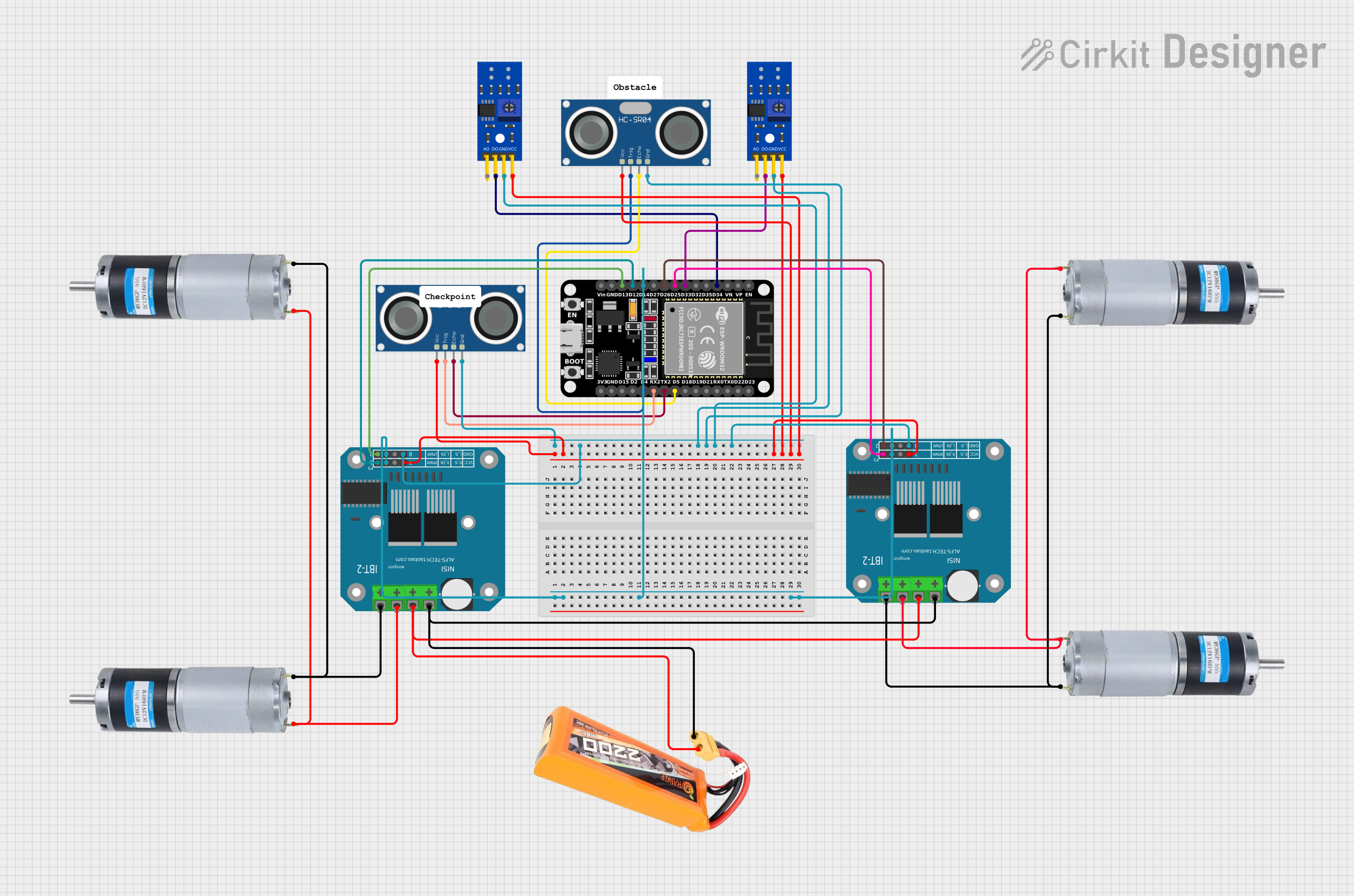
  • Line-following robots for educational and competitive robotics
  • Automated guided vehicles (AGVs) in warehouses
  • Path-following systems in industrial automation
  • Obstacle avoidance and navigation in robotics

Technical Specifications

The following table outlines the key technical details of the Line Tracking Sensor:

Parameter Value
Operating Voltage 3.3V to 5V
Operating Current ≤ 20mA
Detection Range 1mm to 12mm
Output Type Digital (High/Low)
Sensor Type Infrared (IR) Reflective Sensor
Dimensions 32mm x 14mm x 7mm
Weight 3g

Pin Configuration and Descriptions

The Line Tracking Sensor has a 3-pin interface. The pinout is as follows:

Pin Name Description
1 VCC Power supply input (3.3V to 5V)
2 GND Ground connection
3 OUT Digital output signal (High when no line is detected, Low when a line is detected)

Usage Instructions

How to Use the Component in a Circuit

  1. Power the Sensor: Connect the VCC pin to a 3.3V or 5V power source and the GND pin to the ground of your circuit.
  2. Connect the Output: Connect the OUT pin to a digital input pin on your microcontroller (e.g., Arduino UNO).
  3. Position the Sensor: Place the sensor approximately 2-10mm above the surface to ensure accurate line detection.
  4. Calibrate the Sensor: Adjust the sensor's position or sensitivity (if adjustable) to optimize detection for your specific line and surface.

Important Considerations and Best Practices

  • Surface Contrast: Ensure the line has a high contrast with the surrounding surface (e.g., black line on a white surface).
  • Ambient Light: Minimize ambient light interference by using the sensor in controlled lighting conditions.
  • Sensor Placement: Mount the sensor securely to avoid vibrations or misalignment during operation.
  • Multiple Sensors: For complex line-following tasks, use multiple sensors to improve accuracy and responsiveness.

Example Code for Arduino UNO

Below is an example code snippet to interface the Line Tracking Sensor with an Arduino UNO:

// Line Tracking Sensor Example Code
// Manufacturer: Arduinno, Part ID: UNO
// This code reads the sensor's output and prints the status to the Serial Monitor.

const int sensorPin = 2; // Connect the OUT pin of the sensor to digital pin 2

void setup() {
  pinMode(sensorPin, INPUT); // Set the sensor pin as input
  Serial.begin(9600);        // Initialize serial communication at 9600 baud
}

void loop() {
  int sensorValue = digitalRead(sensorPin); // Read the sensor's output
  
  if (sensorValue == LOW) {
    // Line detected
    Serial.println("Line detected!");
  } else {
    // No line detected
    Serial.println("No line detected.");
  }
  
  delay(100); // Small delay for stability
}

Troubleshooting and FAQs

Common Issues and Solutions

  1. Sensor Not Detecting the Line

    • Cause: The sensor is too far from the surface or the line contrast is insufficient.
    • Solution: Adjust the sensor's height to 2-10mm and ensure the line has a high contrast with the surface.
  2. False Positives or Erratic Behavior

    • Cause: Ambient light interference or reflective surfaces.
    • Solution: Use the sensor in a controlled lighting environment and avoid reflective surfaces.
  3. No Output Signal

    • Cause: Incorrect wiring or insufficient power supply.
    • Solution: Verify the connections and ensure the power supply voltage is within the specified range (3.3V to 5V).

FAQs

Q: Can this sensor detect colored lines?
A: The sensor primarily detects contrast, so it works best with black lines on light surfaces or vice versa. It may not reliably detect colored lines with low contrast.

Q: How many sensors should I use for a line-following robot?
A: For basic line-following, one sensor may suffice. However, for better accuracy and complex paths, using two or more sensors is recommended.

Q: Can this sensor be used outdoors?
A: The sensor is sensitive to ambient light, so it is best used indoors or in controlled lighting conditions. For outdoor use, additional shielding may be required.

Q: Is the sensor compatible with other microcontrollers?
A: Yes, the sensor provides a standard digital output, making it compatible with most microcontrollers, including Arduino, Raspberry Pi, and others.