Cirkit Designer Logo
Cirkit Designer
Your all-in-one circuit design IDE
Home / 
Component Documentation

How to Use Lamp Red: Examples, Pinouts, and Specs

Image of Lamp Red
Cirkit Designer LogoDesign with Lamp Red in Cirkit Designer

Introduction

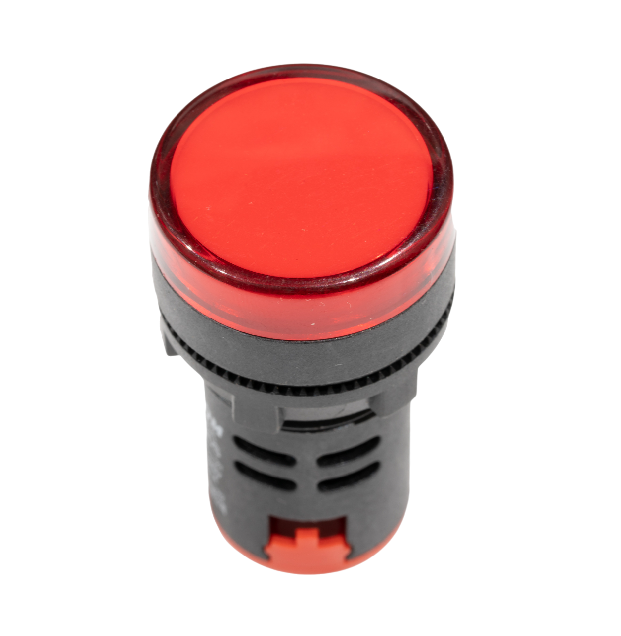
The Red Lamp is a versatile electronic component commonly used as an indicator or for illumination in various circuits. Its bright red light makes it ideal for signaling, status indication, and decorative purposes. This documentation provides detailed information on the Red Lamp, including its technical specifications, usage instructions, and troubleshooting tips.

Explore Projects Built with Lamp Red

Use Cirkit Designer to design, explore, and prototype these projects online. Some projects support real-time simulation. Click "Open Project" to start designing instantly!
Wi-Fi Controlled RGB LED On-Air Lamp with Wemos D1 Mini
Image of OnAir-Lampe: A project utilizing Lamp Red in a practical application
This circuit is an 'On Air' lamp controlled via a Wemos D1 Mini microcontroller. It uses an RGB LED to display different colors and an optocoupler to control an external device, with the microcontroller handling WiFi connectivity and web server functionality to switch the lamp on and off remotely.
Cirkit Designer LogoOpen Project in Cirkit Designer
Light-Activated Relay with LED Indicator
Image of Street Light: A project utilizing Lamp Red in a practical application
This circuit uses a photocell (LDR) to control a 5V relay, which in turn controls the power to a red LED. The relay is powered by a USB plug, and a resistor is used to limit the current to the LED.
Cirkit Designer LogoOpen Project in Cirkit Designer
Battery-Powered Light-Dependent LED Circuit
Image of Automatic street light: A project utilizing Lamp Red in a practical application
This circuit uses a Light Dependent Resistor (LDR) to control a red LED. The LED is powered by a 9V battery, and its brightness varies based on the light intensity detected by the LDR.
Cirkit Designer LogoOpen Project in Cirkit Designer
Toggle Switch Controlled Lamp Circuit with Banana Sockets
Image of STAIRCASE: A project utilizing Lamp Red in a practical application
This circuit consists of two toggle switches and a red lamp connected to panel mount banana sockets. The switches control the connection between the red and black banana sockets, allowing the lamp to be turned on or off depending on the switch positions.
Cirkit Designer LogoOpen Project in Cirkit Designer

Explore Projects Built with Lamp Red

Use Cirkit Designer to design, explore, and prototype these projects online. Some projects support real-time simulation. Click "Open Project" to start designing instantly!
Image of OnAir-Lampe: A project utilizing Lamp Red in a practical application
Wi-Fi Controlled RGB LED On-Air Lamp with Wemos D1 Mini
This circuit is an 'On Air' lamp controlled via a Wemos D1 Mini microcontroller. It uses an RGB LED to display different colors and an optocoupler to control an external device, with the microcontroller handling WiFi connectivity and web server functionality to switch the lamp on and off remotely.
Cirkit Designer LogoOpen Project in Cirkit Designer
Image of Street Light: A project utilizing Lamp Red in a practical application
Light-Activated Relay with LED Indicator
This circuit uses a photocell (LDR) to control a 5V relay, which in turn controls the power to a red LED. The relay is powered by a USB plug, and a resistor is used to limit the current to the LED.
Cirkit Designer LogoOpen Project in Cirkit Designer
Image of Automatic street light: A project utilizing Lamp Red in a practical application
Battery-Powered Light-Dependent LED Circuit
This circuit uses a Light Dependent Resistor (LDR) to control a red LED. The LED is powered by a 9V battery, and its brightness varies based on the light intensity detected by the LDR.
Cirkit Designer LogoOpen Project in Cirkit Designer
Image of STAIRCASE: A project utilizing Lamp Red in a practical application
Toggle Switch Controlled Lamp Circuit with Banana Sockets
This circuit consists of two toggle switches and a red lamp connected to panel mount banana sockets. The switches control the connection between the red and black banana sockets, allowing the lamp to be turned on or off depending on the switch positions.
Cirkit Designer LogoOpen Project in Cirkit Designer

Technical Specifications

Parameter Value
Manufacturer [Manufacturer Name]
Part ID [Part ID]
Color Red
Operating Voltage 2V - 2.2V
Forward Current 20mA
Power Dissipation 44mW
Wavelength 620-630nm
Viewing Angle 30°
Package Type Through-hole

Pin Configuration

Pin Description
Anode Positive terminal (+)
Cathode Negative terminal (-)

Usage Instructions

Connecting the Red Lamp in a Circuit

  1. Identify the Pins: The Red Lamp has two pins: the Anode (longer pin) and the Cathode (shorter pin).
  2. Connect to Power Source: Connect the Anode to the positive terminal of the power source and the Cathode to the negative terminal.
  3. Use a Current-Limiting Resistor: To prevent damage, use a resistor in series with the lamp. Calculate the resistor value using Ohm's Law: [ R = \frac{V_{supply} - V_{forward}}{I_{forward}} ] For example, with a 5V supply and a forward voltage of 2V: [ R = \frac{5V - 2V}{20mA} = 150\Omega ]

Example Circuit with Arduino UNO

To control the Red Lamp using an Arduino UNO, connect the Anode to a digital pin and the Cathode to the ground (GND) through a current-limiting resistor.

Circuit Diagram

Arduino UNO
+5V ----->|----[150Ω]-----> GND
          |
         Pin 13

Arduino Code

// Red Lamp connected to digital pin 13
const int lampPin = 13;

void setup() {
  // Initialize the digital pin as an output
  pinMode(lampPin, OUTPUT);
}

void loop() {
  // Turn the lamp on
  digitalWrite(lampPin, HIGH);
  delay(1000); // Wait for 1 second

  // Turn the lamp off
  digitalWrite(lampPin, LOW);
  delay(1000); // Wait for 1 second
}

Important Considerations and Best Practices

  • Current Limiting: Always use a current-limiting resistor to prevent excessive current flow.
  • Polarity: Ensure correct polarity when connecting the lamp to avoid damage.
  • Heat Dissipation: Avoid operating the lamp at maximum current for extended periods to prevent overheating.

Troubleshooting and FAQs

Common Issues

  1. Lamp Does Not Light Up

    • Solution: Check the power supply and ensure correct polarity. Verify the resistor value and connections.
  2. Lamp Flickers

    • Solution: Ensure stable power supply and secure connections. Check for loose wires or poor solder joints.
  3. Lamp Burns Out Quickly

    • Solution: Verify the current-limiting resistor value. Ensure the current does not exceed the rated forward current.

FAQs

Q: Can I use the Red Lamp with a 3.3V power supply?

  • A: Yes, you can use a 3.3V power supply. Adjust the resistor value accordingly to limit the current.

Q: What is the maximum current the Red Lamp can handle?

  • A: The maximum forward current is 20mA. Exceeding this can damage the lamp.

Q: Can I use the Red Lamp for AC applications?

  • A: The Red Lamp is designed for DC applications. Using it with AC may require additional components like rectifiers.

By following this documentation, users can effectively integrate the Red Lamp into their electronic projects, ensuring optimal performance and longevity.