How to Use HEF4013B: Examples, Pinouts, and Specs
Introduction
The HEF4013B is a dual D-type flip-flop integrated circuit (IC) that features two identical, independent flip-flops with data, clock, and reset inputs. This IC is widely used in digital electronics for latching, storing bits, edge detection, and building counters and shift registers. Its ability to maintain a binary state makes it essential for sequential logic circuits.
Explore Projects Built with HEF4013B


Explore Projects Built with HEF4013B
Common Applications
- Data storage
- Signal synchronization
- Flip-flop based counters
- Shift registers
- Bounce elimination for mechanical switches
- Frequency division
Technical Specifications
Key Technical Details
- Supply Voltage (V_DD): 3 V to 15 V
- Input Voltage (V_I): -0.5 V to V_DD + 0.5 V
- Output Voltage (V_O): -0.5 V to V_DD + 0.5 V
- Output Current (I_O): ±10 mA
- Power Dissipation (P_tot): 500 mW
- Operating Temperature Range (T_amb): -40 °C to +85 °C
- Propagation Delay Time (t_pd): 30 ns (typical at V_DD = 10 V)
- Set-up Time (t_su): 20 ns (minimum at V_DD = 10 V)
- Clock Frequency (f_clk): 30 MHz (maximum at V_DD = 15 V)
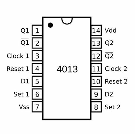
Pin Configuration and Descriptions
| Pin Number | Name | Description |
|---|---|---|
| 1 | Q1 | Output of flip-flop 1 (non-inverted) |
| 2 | Q1' | Output of flip-flop 1 (inverted) |
| 3 | RST1 | Reset input for flip-flop 1 (active HIGH) |
| 4 | D1 | Data input for flip-flop 1 |
| 5 | CLK1 | Clock input for flip-flop 1 |
| 6 | - | Not connected (NC) |
| 7 | V_SS | Ground (0 V) |
| 8 | CLK2 | Clock input for flip-flop 2 |
| 9 | D2 | Data input for flip-flop 2 |
| 10 | RST2 | Reset input for flip-flop 2 (active HIGH) |
| 11 | Q2' | Output of flip-flop 2 (inverted) |
| 12 | Q2 | Output of flip-flop 2 (non-inverted) |
| 13 | - | Not connected (NC) |
| 14 | V_DD | Positive supply voltage |
Usage Instructions
How to Use the HEF4013B in a Circuit
- Power Supply: Connect pin 14 (V_DD) to the positive supply voltage within the specified range and pin 7 (V_SS) to the ground.
- Input Connections: Apply the data signal to D1 or D2 for the respective flip-flop. The clock signal should be connected to CLK1 or CLK2, and the reset signal to RST1 or RST2 if needed.
- Output Monitoring: The state of the flip-flop can be observed at Q1, Q1', Q2, and Q2' pins.
Important Considerations and Best Practices
- Ensure that the supply voltage does not exceed the recommended maximum to prevent damage.
- Inputs should not be left floating; they should be connected to a known logic level.
- Avoid applying signals to inputs while the IC is powered off to prevent unintended current flow.
- Use a pull-up or pull-down resistor on the reset pin if it is not actively driven.
- Decoupling capacitors (e.g., 0.1 µF) should be placed close to the IC's power supply pins to filter out noise.
Troubleshooting and FAQs
Common Issues
- Unstable Outputs: This can be caused by floating inputs or noise in the clock signal. Ensure all inputs are tied to a valid logic level and that the clock signal is clean.
- Unexpected Resets: Check the reset line for noise or unintended signals that might be triggering a reset.
Solutions and Tips
- Floating Inputs: Connect unused inputs to V_DD or V_SS through a resistor to define their state.
- Noise Suppression: Use a low-pass filter or a Schmitt trigger to clean up noisy signals before they reach the clock or reset inputs.
FAQs
Q: Can the HEF4013B be used with an Arduino? A: Yes, the HEF4013B can be interfaced with an Arduino, provided the voltage levels are compatible.
Q: What is the maximum frequency the HEF4013B can handle? A: The maximum clock frequency is 30 MHz at V_DD = 15 V, but it decreases with lower supply voltages.
Q: How do I reset the flip-flop? A: Apply a HIGH signal to the reset input (RST1 or RST2) to reset the respective flip-flop.
Example Arduino Connection and Code
// Define the Arduino pins connected to the HEF4013B
const int dataPin = 2;    // Connected to D1
const int clockPin = 3;   // Connected to CLK1
const int resetPin = 4;   // Connected to RST1

void setup() {
  pinMode(dataPin, OUTPUT);
  pinMode(clockPin, OUTPUT);
  pinMode(resetPin, OUTPUT);

  // Reset the flip-flop at the start
  digitalWrite(resetPin, HIGH);
  delay(10);
  digitalWrite(resetPin, LOW);
}

void loop() {
  // Set data to HIGH
  digitalWrite(dataPin, HIGH);
  // Toggle the clock to store the data
  digitalWrite(clockPin, HIGH);
  delay(10); // Wait for a short period
  digitalWrite(clockPin, LOW);
  delay(1000); // Wait for 1 second

  // Reset the flip-flop
  digitalWrite(resetPin, HIGH);
  delay(10);
  digitalWrite(resetPin, LOW);
  delay(1000); // Wait for 1 second before the next loop iteration
}
This example demonstrates how to interface the HEF4013B with an Arduino to set and reset the flip-flop. Ensure that the voltage levels are compatible and use level shifters if necessary.