Cirkit Designer Logo
Cirkit Designer
Your all-in-one circuit design IDE
Home / 
Component Documentation

How to Use ICS-43434: Examples, Pinouts, and Specs

Image of ICS-43434
Cirkit Designer LogoDesign with ICS-43434 in Cirkit Designer

Introduction

The ICS-43434 is a high-performance, low-power digital MEMS (Micro-Electro-Mechanical Systems) microphone designed for audio applications. It features a small form factor, high signal-to-noise ratio (SNR), and low power consumption, making it ideal for use in portable devices such as smartphones, tablets, and wearable electronics. The ICS-43434 outputs audio data in a Pulse Density Modulation (PDM) format, which is commonly used in digital audio systems.

Explore Projects Built with ICS-43434

Use Cirkit Designer to design, explore, and prototype these projects online. Some projects support real-time simulation. Click "Open Project" to start designing instantly!
Logic Gate Circuit with 7408 AND and 7432 OR ICs
Image of gate: A project utilizing ICS-43434 in a practical application
This circuit includes a 7408 AND gate IC and a 7432 OR gate IC, both powered by a common VCC and GND connection. The circuit is designed to perform basic logical operations, combining AND and OR gates for digital signal processing.
Cirkit Designer LogoOpen Project in Cirkit Designer
Satellite-Based Timing and Navigation System with SDR and Atomic Clock Synchronization
Image of GPS 시스템 측정 구성도_Confirm: A project utilizing ICS-43434 in a practical application
This circuit appears to be a complex system involving power supply management, GPS and timing synchronization, and data communication. It includes a SI-TEX G1 Satellite Compass for GPS data, an XHTF1021 Atomic Rubidium Clock for precise timing, and Ettus USRP B200 units for software-defined radio communication. Power is supplied through various SMPS units and distributed via terminal blocks and DC jacks. Data communication is facilitated by Beelink MINI S12 N95 computers, RS232 splitters, and a 1000BASE-T Media Converter for network connectivity. RF Directional Couplers are used to interface antennas with the USRP units, and the entire system is likely contained within cases for protection and organization.
Cirkit Designer LogoOpen Project in Cirkit Designer
Cellular-Enabled IoT Device with Real-Time Clock and Power Management
Image of LRCM PHASE 2 BASIC: A project utilizing ICS-43434 in a practical application
This circuit features a LilyGo-SIM7000G module for cellular communication and GPS functionality, interfaced with an RTC DS3231 for real-time clock capabilities. It includes voltage sensing through two voltage sensor modules, and uses an 8-channel opto-coupler for isolating different parts of the circuit. Power management is handled by a buck converter connected to a DC power source and batteries, with a fuse for protection and a rocker switch for on/off control. Additionally, there's an LED for indication purposes.
Cirkit Designer LogoOpen Project in Cirkit Designer
ESP32-Based Security System with RFID and Laser Intrusion Detection
Image of CPE doorlock system upgrade: A project utilizing ICS-43434 in a practical application
This circuit is a security and access control system featuring motion detection, laser beam-break sensing, and RFID scanning, interfaced with a keypad and visual/audible indicators, powered by a solar-charged battery, and capable of controlling an electric lock via a relay.
Cirkit Designer LogoOpen Project in Cirkit Designer

Explore Projects Built with ICS-43434

Use Cirkit Designer to design, explore, and prototype these projects online. Some projects support real-time simulation. Click "Open Project" to start designing instantly!
Image of gate: A project utilizing ICS-43434 in a practical application
Logic Gate Circuit with 7408 AND and 7432 OR ICs
This circuit includes a 7408 AND gate IC and a 7432 OR gate IC, both powered by a common VCC and GND connection. The circuit is designed to perform basic logical operations, combining AND and OR gates for digital signal processing.
Cirkit Designer LogoOpen Project in Cirkit Designer
Image of GPS 시스템 측정 구성도_Confirm: A project utilizing ICS-43434 in a practical application
Satellite-Based Timing and Navigation System with SDR and Atomic Clock Synchronization
This circuit appears to be a complex system involving power supply management, GPS and timing synchronization, and data communication. It includes a SI-TEX G1 Satellite Compass for GPS data, an XHTF1021 Atomic Rubidium Clock for precise timing, and Ettus USRP B200 units for software-defined radio communication. Power is supplied through various SMPS units and distributed via terminal blocks and DC jacks. Data communication is facilitated by Beelink MINI S12 N95 computers, RS232 splitters, and a 1000BASE-T Media Converter for network connectivity. RF Directional Couplers are used to interface antennas with the USRP units, and the entire system is likely contained within cases for protection and organization.
Cirkit Designer LogoOpen Project in Cirkit Designer
Image of LRCM PHASE 2 BASIC: A project utilizing ICS-43434 in a practical application
Cellular-Enabled IoT Device with Real-Time Clock and Power Management
This circuit features a LilyGo-SIM7000G module for cellular communication and GPS functionality, interfaced with an RTC DS3231 for real-time clock capabilities. It includes voltage sensing through two voltage sensor modules, and uses an 8-channel opto-coupler for isolating different parts of the circuit. Power management is handled by a buck converter connected to a DC power source and batteries, with a fuse for protection and a rocker switch for on/off control. Additionally, there's an LED for indication purposes.
Cirkit Designer LogoOpen Project in Cirkit Designer
Image of CPE doorlock system upgrade: A project utilizing ICS-43434 in a practical application
ESP32-Based Security System with RFID and Laser Intrusion Detection
This circuit is a security and access control system featuring motion detection, laser beam-break sensing, and RFID scanning, interfaced with a keypad and visual/audible indicators, powered by a solar-charged battery, and capable of controlling an electric lock via a relay.
Cirkit Designer LogoOpen Project in Cirkit Designer

Common Applications and Use Cases

  • Smartphones and tablets
  • Wearable devices
  • Smart home devices (e.g., voice assistants)
  • Audio recording and processing systems
  • Noise-canceling systems
  • IoT devices with voice input functionality

Technical Specifications

The ICS-43434 is designed to deliver high-quality audio performance while maintaining low power consumption. Below are the key technical details:

Key Specifications

Parameter Value
Supply Voltage (VDD) 1.62V to 3.63V
Signal-to-Noise Ratio (SNR) 65 dB (typical)
Acoustic Overload Point 120 dB SPL
Sensitivity -26 dBFS ±1 dB
Power Consumption 650 µA (typical)
Output Format Pulse Density Modulation (PDM)
Operating Temperature Range -40°C to +85°C
Dimensions 3.5 mm x 2.65 mm x 0.98 mm

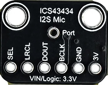
Pin Configuration and Descriptions

The ICS-43434 has a total of 5 pins. The table below describes each pin and its function:

Pin Name Pin Number Description
VDD 1 Power supply input (1.62V to 3.63V).
GND 2 Ground connection.
DATA 3 PDM data output.
CLK 4 Clock input for PDM interface.
LRSEL 5 Left/Right channel select. Connect to GND for left channel or VDD for right channel.

Usage Instructions

The ICS-43434 is straightforward to use in digital audio systems. Below are the steps and considerations for integrating it into a circuit:

Circuit Integration

  1. Power Supply: Connect the VDD pin to a stable power supply within the range of 1.62V to 3.63V. Connect the GND pin to the ground of the circuit.
  2. Clock Signal: Provide a clock signal (CLK) to the microphone. The clock frequency should typically range from 1 MHz to 3.25 MHz.
  3. Data Output: The PDM audio data is output through the DATA pin. This data can be processed by a microcontroller or digital signal processor (DSP).
  4. Channel Selection: Use the LRSEL pin to configure the microphone as either the left or right channel in a stereo setup:
    • Connect LRSEL to GND for the left channel.
    • Connect LRSEL to VDD for the right channel.

Important Considerations

  • Decoupling Capacitor: Place a 0.1 µF decoupling capacitor close to the VDD pin to reduce noise and ensure stable operation.
  • Clock Signal Quality: Ensure the clock signal is clean and within the specified frequency range to avoid audio distortion.
  • PCB Layout: Minimize the trace length for the DATA and CLK lines to reduce signal degradation and noise interference.

Example: Connecting ICS-43434 to an Arduino UNO

The ICS-43434 can be connected to an Arduino UNO for basic audio data acquisition. Below is an example wiring and code snippet:

Wiring

ICS-43434 Pin Arduino UNO Pin
VDD 3.3V
GND GND
DATA Digital Pin 2
CLK Digital Pin 3
LRSEL GND (Left)

Arduino Code

// Example code for reading PDM data from ICS-43434 using Arduino UNO
// Note: This example assumes the use of an external PDM library for processing.

#include <PDM.h> // Include a PDM library for handling PDM data

// Buffer to store PDM data
#define BUFFER_SIZE 256
int16_t pdmBuffer[BUFFER_SIZE];

// Callback function to handle incoming PDM data
void onPDMData() {
  // Read PDM data into the buffer
  int bytesAvailable = PDM.available();
  PDM.read(pdmBuffer, bytesAvailable);
  
  // Process the PDM data (e.g., convert to PCM or analyze audio)
  // Add your audio processing code here
}

void setup() {
  // Initialize serial communication for debugging
  Serial.begin(9600);
  
  // Configure PDM microphone
  if (!PDM.begin(1, 16000)) { // Mono channel, 16 kHz sample rate
    Serial.println("Failed to initialize PDM microphone!");
    while (1);
  }
  
  // Set the callback function for PDM data
  PDM.onReceive(onPDMData);
  
  Serial.println("PDM microphone initialized successfully.");
}

void loop() {
  // Main loop does nothing; PDM data is handled in the callback
}

Troubleshooting and FAQs

Common Issues

  1. No Audio Output:

    • Ensure the clock signal is being provided to the CLK pin.
    • Verify that the VDD and GND connections are secure.
    • Check the LRSEL pin configuration for the correct channel selection.
  2. Distorted Audio:

    • Verify that the clock frequency is within the specified range (1 MHz to 3.25 MHz).
    • Ensure the decoupling capacitor is properly placed near the VDD pin.
  3. High Noise Levels:

    • Minimize the length of the DATA and CLK traces on the PCB.
    • Ensure proper grounding to reduce interference.

FAQs

Q: Can the ICS-43434 be used in a stereo configuration?
A: Yes, you can use two ICS-43434 microphones in a stereo setup by configuring one microphone as the left channel (LRSEL = GND) and the other as the right channel (LRSEL = VDD).

Q: What is the maximum distance between the microphone and the microcontroller?
A: To minimize signal degradation, keep the DATA and CLK lines as short as possible, ideally less than 10 cm.

Q: Does the ICS-43434 support analog output?
A: No, the ICS-43434 outputs digital audio data in PDM format only.