
How to Use uM-FPUv2: Examples, Pinouts, and Specs
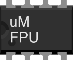
 Design with uM-FPUv2 in Cirkit Designer
Introduction
The uM-FPUv2 is a compact floating-point unit (FPU) designed to work seamlessly with microcontrollers. It provides hardware acceleration for floating-point arithmetic operations, enabling efficient and precise calculations in embedded systems. By offloading complex mathematical computations to the uM-FPUv2, microcontrollers can focus on other tasks, improving overall system performance.
Explore Projects Built with uM-FPUv2
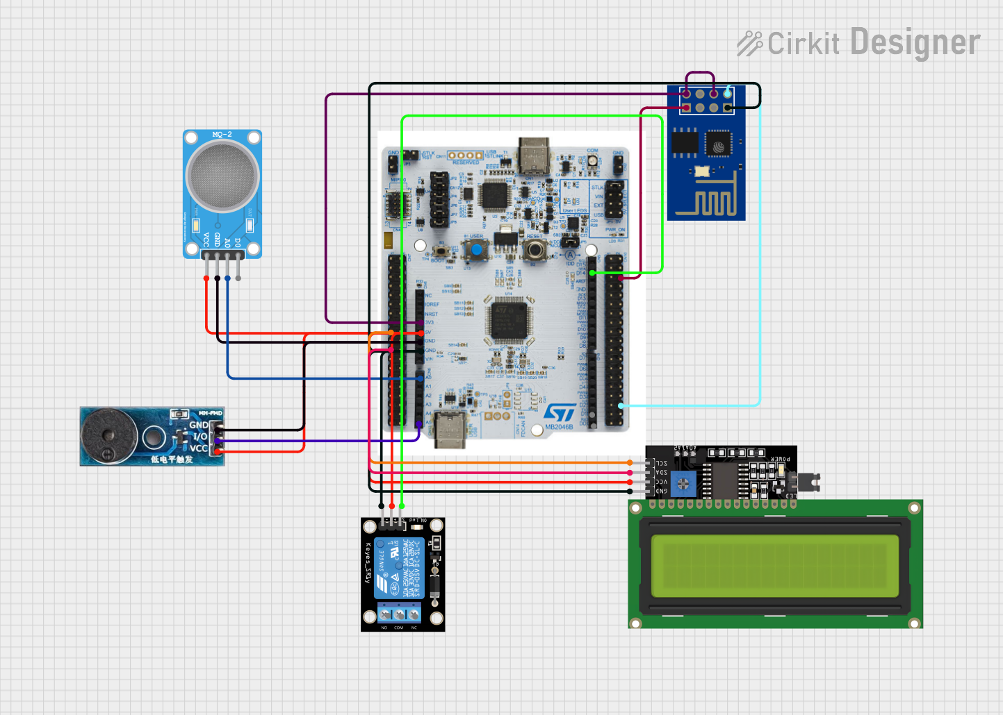 Open Project in Cirkit Designer
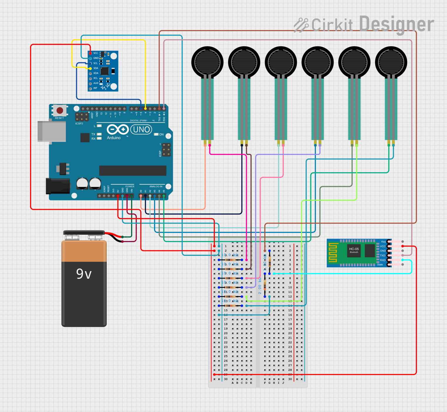 Open Project in Cirkit Designer
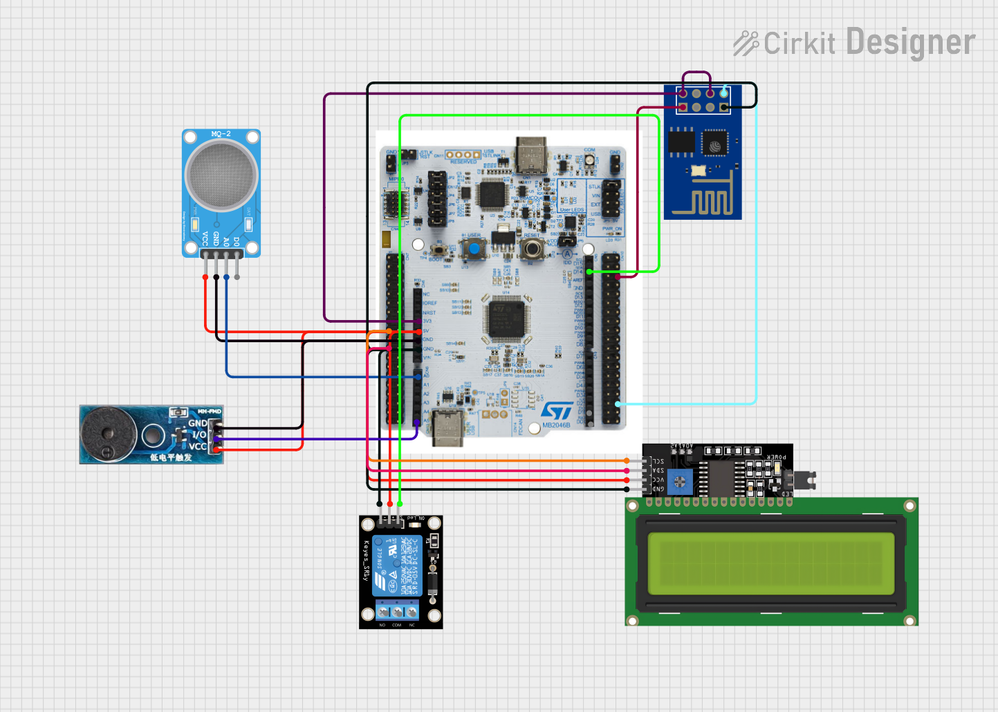 Open Project in Cirkit Designer
 Open Project in Cirkit Designer
Explore Projects Built with uM-FPUv2
Open Project in Cirkit DesignerOpen Project in Cirkit DesignerOpen Project in Cirkit DesignerOpen Project in Cirkit DesignerCommon Applications and Use Cases
- Robotics: Real-time control systems requiring precise calculations.
- Signal Processing: Applications involving FFTs, filtering, or other mathematical operations.
- Data Acquisition: Systems requiring high-precision data analysis.
- Embedded AI/ML: Lightweight machine learning models with floating-point operations.
- Scientific Instruments: Devices requiring accurate and fast floating-point computations.
Technical Specifications
Key Technical Details
- Supply Voltage (Vcc): 3.3V to 5.0V
- Operating Current: ~10mA
- Communication Interface: I²C or SPI
- Clock Speed: Up to 32 MHz
- Floating-Point Format: IEEE 754 single-precision (32-bit)
- Instruction Set: Supports arithmetic, trigonometric, logarithmic, and exponential functions.
- Package Type: 14-pin DIP or SOIC
Pin Configuration and Descriptions
The uM-FPUv2 has 14 pins, with the following configuration:
| Pin Number | Pin Name | Description |
|---|---|---|
| 1 | Vcc | Power supply input (3.3V to 5.0V). |
| 2 | GND | Ground connection. |
| 3 | SCL/CLK | I²C clock line (SCL) or SPI clock (CLK), depending on the communication mode. |
| 4 | SDA/MOSI | I²C data line (SDA) or SPI Master Out Slave In (MOSI). |
| 5 | MISO | SPI Master In Slave Out (MISO). |
| 6 | CS | SPI Chip Select (active low). |
| 7 | INT | Interrupt output, used to signal the completion of operations. |
| 8 | RESET | Resets the FPU to its initial state. |
| 9-14 | NC | No connection (reserved for future use). |
Usage Instructions
How to Use the uM-FPUv2 in a Circuit
- Power Supply: Connect the Vcc pin to a 3.3V or 5.0V power source and the GND pin to ground.
- Communication Mode: Decide whether to use I²C or SPI for communication:
- For I²C, connect the SCL and SDA pins to the corresponding microcontroller pins.
- For SPI, connect the CLK, MOSI, MISO, and CS pins to the respective SPI pins on the microcontroller.
- Pull-Up Resistors (I²C): Use pull-up resistors (typically 4.7kΩ) on the SCL and SDA lines.
- Interrupt Handling: Connect the INT pin to a microcontroller GPIO pin if you want to use interrupts.
- Reset: Optionally, connect the RESET pin to a microcontroller GPIO pin for manual resets.
Important Considerations and Best Practices
- Ensure the supply voltage matches the microcontroller's logic level (3.3V or 5.0V).
- Use decoupling capacitors (e.g., 0.1µF) near the Vcc pin to reduce noise.
- For SPI communication, ensure the CS pin is properly toggled to select the FPU.
- Avoid leaving unused pins floating; connect them to GND if not in use.
Example Code for Arduino UNO (I²C Communication)
#include <Wire.h> // Include the Wire library for I²C communication

#define FPU_ADDRESS 0x60 // Default I²C address of the uM-FPUv2

void setup() {
  Wire.begin(); // Initialize I²C communication
  Serial.begin(9600); // Initialize serial communication for debugging

  // Send a reset command to the uM-FPUv2
  Wire.beginTransmission(FPU_ADDRESS);
  Wire.write(0x01); // Example command: Reset the FPU
  Wire.endTransmission();

  Serial.println("uM-FPUv2 initialized.");
}

void loop() {
  // Example: Send a floating-point number to the FPU
  float number = 3.14;
  byte* bytePointer = (byte*)&number; // Convert float to byte array

  Wire.beginTransmission(FPU_ADDRESS);
  Wire.write(0x10); // Example command: Load a floating-point number
  for (int i = 0; i < 4; i++) {
    Wire.write(bytePointer[i]); // Send each byte of the float
  }
  Wire.endTransmission();

  Serial.println("Number sent to uM-FPUv2.");
  delay(1000); // Wait for 1 second
}
Troubleshooting and FAQs
Common Issues and Solutions
The FPU is not responding:
- Verify the power supply voltage and connections.
- Check the communication mode (I²C or SPI) and ensure the wiring matches.
- Ensure pull-up resistors are present on the I²C lines.
Incorrect results from calculations:
- Confirm that the input data is formatted correctly (e.g., IEEE 754 for floating-point numbers).
- Check for communication errors or incomplete data transmission.
Interrupts not working:
- Ensure the INT pin is connected to a microcontroller GPIO pin.
- Verify that the microcontroller is configured to handle external interrupts.
Reset pin not functioning:
- Ensure the RESET pin is connected to a GPIO pin or tied to a known state.
- Check for proper initialization after a reset.
FAQs
Q: Can the uM-FPUv2 handle double-precision floating-point numbers?
A: No, the uM-FPUv2 supports only single-precision (32-bit) floating-point numbers as per the IEEE 754 standard.
Q: What is the maximum clock speed for SPI communication?
A: The uM-FPUv2 supports SPI clock speeds of up to 32 MHz.
Q: Can I use the uM-FPUv2 with 3.3V and 5.0V systems?
A: Yes, the uM-FPUv2 is compatible with both 3.3V and 5.0V systems, but ensure the logic levels match your microcontroller.
Q: Is the uM-FPUv2 compatible with all microcontrollers?
A: The uM-FPUv2 is compatible with most microcontrollers that support I²C or SPI communication. Always check the datasheet for specific requirements.