
How to Use NC7WZ07: Examples, Pinouts, and Specs
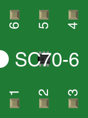
 Design with NC7WZ07 in Cirkit Designer
Introduction
The NC7WZ07 is a single Schmitt-trigger buffer designed for high-speed operation in digital circuits. It features a Schmitt-trigger input, which ensures clean and stable transitions even with slow or noisy input signals. This component is particularly useful for improving signal integrity, interfacing between different logic levels, and driving capacitive loads. Its compact design and robust performance make it a popular choice in a wide range of applications.
Explore Projects Built with NC7WZ07
 Open Project in Cirkit Designer
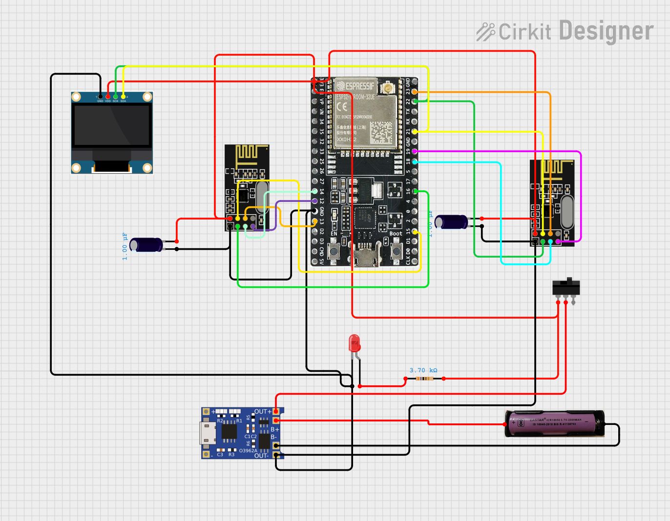 Open Project in Cirkit Designer
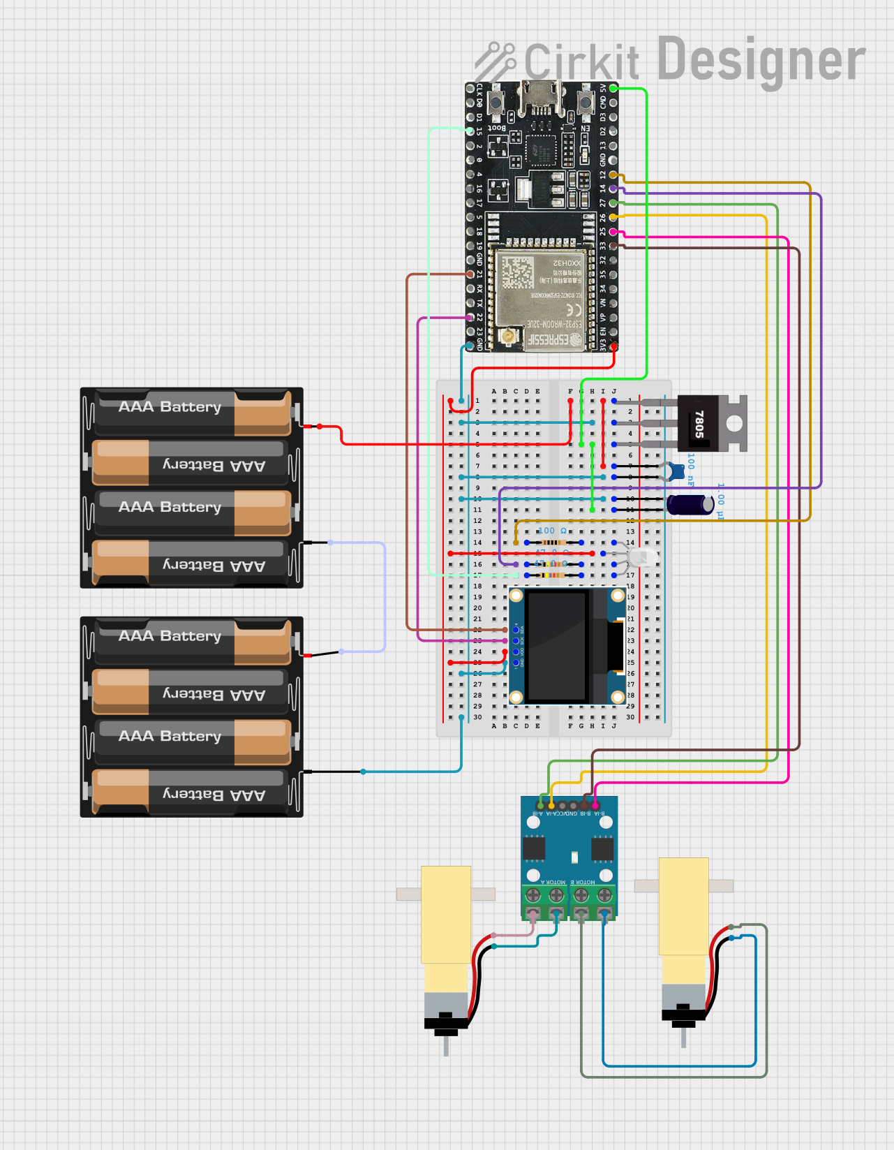 Open Project in Cirkit Designer
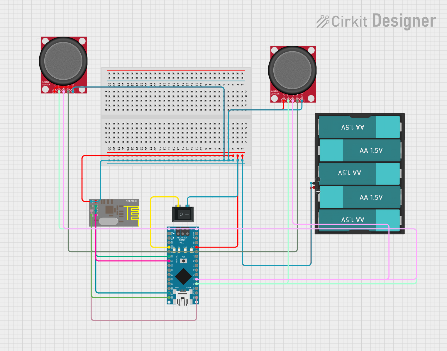 Open Project in Cirkit Designer
Explore Projects Built with NC7WZ07
Open Project in Cirkit DesignerOpen Project in Cirkit DesignerOpen Project in Cirkit DesignerOpen Project in Cirkit DesignerCommon Applications and Use Cases
- Signal conditioning and noise filtering
- Interfacing between different logic families (e.g., TTL to CMOS)
- Driving capacitive loads or long transmission lines
- Pulse shaping and waveform generation
- Digital circuits requiring fast rise and fall times
Technical Specifications
Key Technical Details
- Supply Voltage (Vcc): 1.65V to 5.5V
- Input Voltage (Vin): 0V to 5.5V
- Output Voltage (Vout): 0V to 5.5V
- Output Current (Iout): ±24mA (maximum)
- Propagation Delay (tpd): 2.5ns (typical at 3.3V)
- Input Threshold Voltage (Vt+ / Vt-): Dependent on Vcc (Schmitt-trigger hysteresis)
- Operating Temperature Range: -40°C to +85°C
- Package Options: SOT-23, SC-70, and other small-outline packages
Pin Configuration and Descriptions
The NC7WZ07 is typically available in a 5-pin SOT-23 or SC-70 package. Below is the pinout and description:
| Pin Number | Pin Name | Description |
|---|---|---|
| 1 | A | Input signal |
| 2 | GND | Ground (0V reference) |
| 3 | Y | Output signal (open-drain configuration) |
| 4 | Vcc | Positive supply voltage |
| 5 | NC | No connection (not internally connected) |
Note: The output (Y) is open-drain, meaning it requires an external pull-up resistor to function correctly.
Usage Instructions
How to Use the NC7WZ07 in a Circuit
- Power Supply: Connect the Vcc pin to a stable power supply within the range of 1.65V to 5.5V. Connect the GND pin to the circuit ground.
- Input Signal: Apply the input signal to the A pin. The Schmitt-trigger input ensures clean transitions even with noisy or slow signals.
- Output Signal: The Y pin provides the buffered output. Since it is open-drain, connect a pull-up resistor (typically 10kΩ) between the Y pin and Vcc to ensure proper operation.
- Interfacing Logic Levels: Use the NC7WZ07 to interface between different logic families by ensuring the input and output voltage levels are compatible with the connected devices.
- Driving Loads: The NC7WZ07 can drive capacitive loads or long transmission lines due to its high output current capability and fast switching speed.
Important Considerations and Best Practices
- Pull-Up Resistor: Always use an appropriate pull-up resistor on the output pin (Y) to ensure proper operation of the open-drain output.
- Input Voltage Range: Ensure the input voltage does not exceed the specified range (0V to 5.5V) to avoid damage to the component.
- Bypass Capacitor: Place a 0.1µF ceramic capacitor close to the Vcc pin to filter noise and stabilize the power supply.
- Unused Pins: If any input pins are unused, connect them to GND or Vcc to prevent floating inputs, which can cause erratic behavior.
Example: Using NC7WZ07 with Arduino UNO
The NC7WZ07 can be used to buffer signals between an Arduino UNO and other devices. Below is an example of interfacing the NC7WZ07 with an Arduino to drive an LED.
// Example: Using NC7WZ07 to drive an LED with Arduino UNO

const int inputPin = 2;  // Arduino pin connected to NC7WZ07 input (A)
const int ledPin = 3;    // Arduino pin connected to NC7WZ07 output (Y)

void setup() {
  pinMode(inputPin, OUTPUT); // Set inputPin as output to drive NC7WZ07
  pinMode(ledPin, OUTPUT);   // Set ledPin as output for LED
}

void loop() {
  digitalWrite(inputPin, HIGH); // Send HIGH signal to NC7WZ07 input
  delay(500);                   // Wait for 500ms
  digitalWrite(inputPin, LOW);  // Send LOW signal to NC7WZ07 input
  delay(500);                   // Wait for 500ms
}
Note: Connect a pull-up resistor (e.g., 10kΩ) between the NC7WZ07 output (Y) and Vcc. The LED should be connected in series with a current-limiting resistor to prevent damage.
Troubleshooting and FAQs
Common Issues and Solutions
No Output Signal:
- Cause: Missing or incorrect pull-up resistor on the output pin.
- Solution: Ensure a pull-up resistor (e.g., 10kΩ) is connected between the output pin (Y) and Vcc.
Erratic Behavior:
- Cause: Floating input pins or insufficient power supply decoupling.
- Solution: Tie unused input pins to GND or Vcc, and add a 0.1µF bypass capacitor near the Vcc pin.
Slow Response Time:
- Cause: Excessive capacitance on the output or incorrect pull-up resistor value.
- Solution: Use a lower-value pull-up resistor (e.g., 4.7kΩ) to improve switching speed.
Component Overheating:
- Cause: Exceeding the maximum output current rating.
- Solution: Ensure the load does not draw more than ±24mA from the output pin.
FAQs
Q: Can the NC7WZ07 be used with 3.3V and 5V logic levels?
A: Yes, the NC7WZ07 supports a wide supply voltage range (1.65V to 5.5V) and can interface between 3.3V and 5V logic levels.Q: What is the purpose of the Schmitt-trigger input?
A: The Schmitt-trigger input ensures clean and stable transitions, even with slow or noisy input signals, improving signal integrity.Q: Can I leave the NC pin unconnected?
A: Yes, the NC pin is not internally connected and can be left floating without affecting the operation of the component.Q: What is the maximum frequency the NC7WZ07 can handle?
A: The NC7WZ07 can handle high-speed signals with a typical propagation delay of 2.5ns at 3.3V, making it suitable for frequencies in the MHz range.