How to Use L293 DC and Stepper motro driver: Examples, Pinouts, and Specs
Introduction
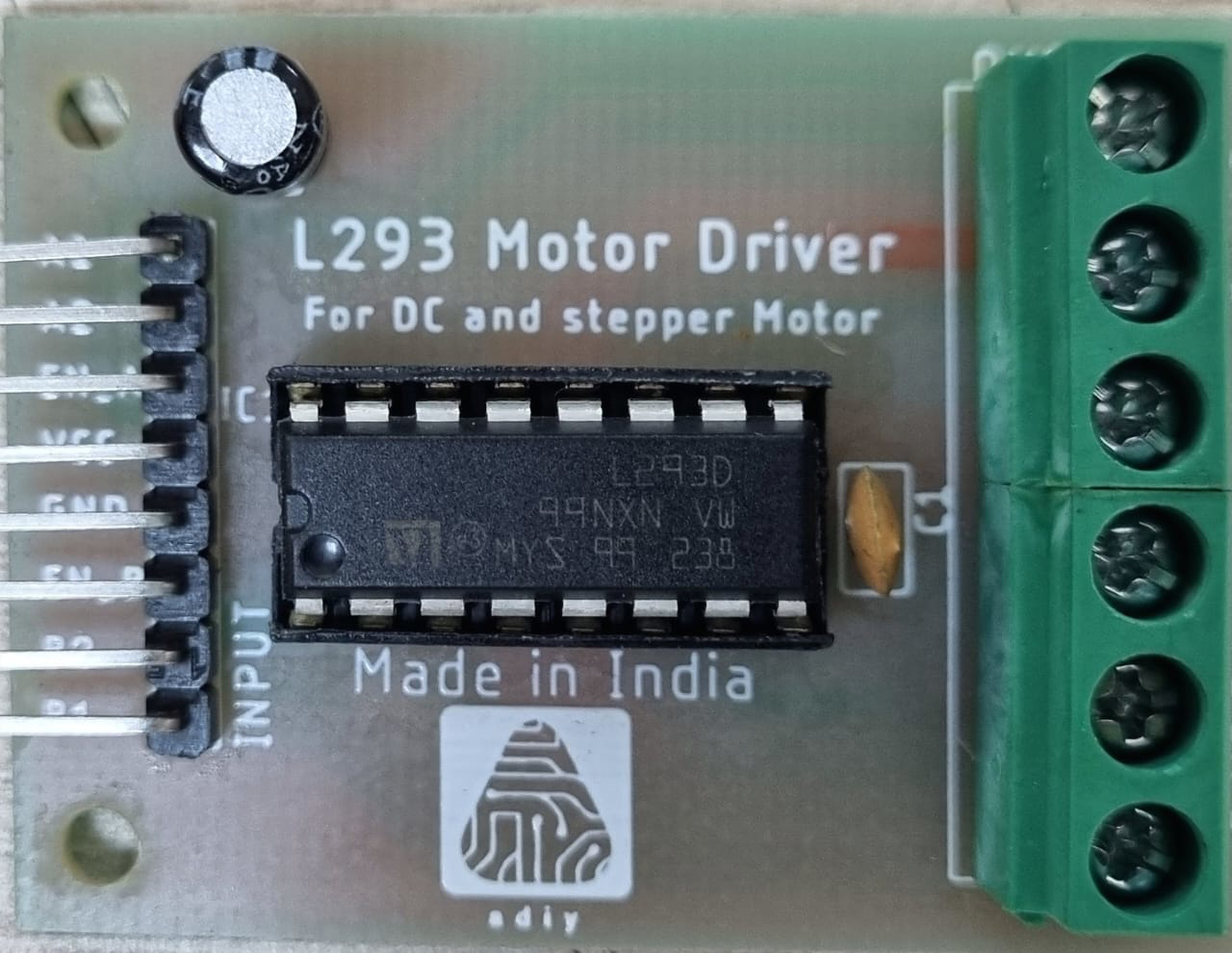
The L293 is a dual H-bridge motor driver IC designed to control DC and stepper motors. It enables bidirectional control, allowing motors to rotate in both clockwise and counterclockwise directions. With the ability to drive two motors simultaneously, the L293 is a versatile component widely used in robotics, automation, and motor control applications. It can handle up to 600mA of current per channel and operates at a wide voltage range, making it suitable for a variety of projects.
Explore Projects Built with L293 DC and Stepper motro driver
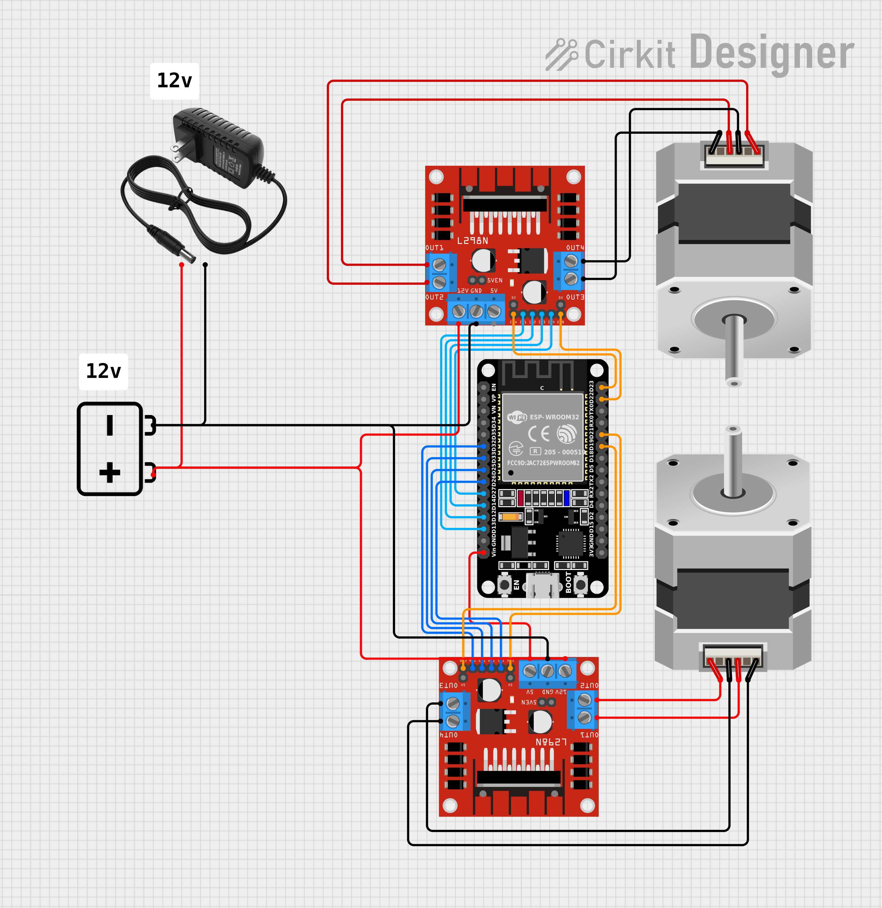
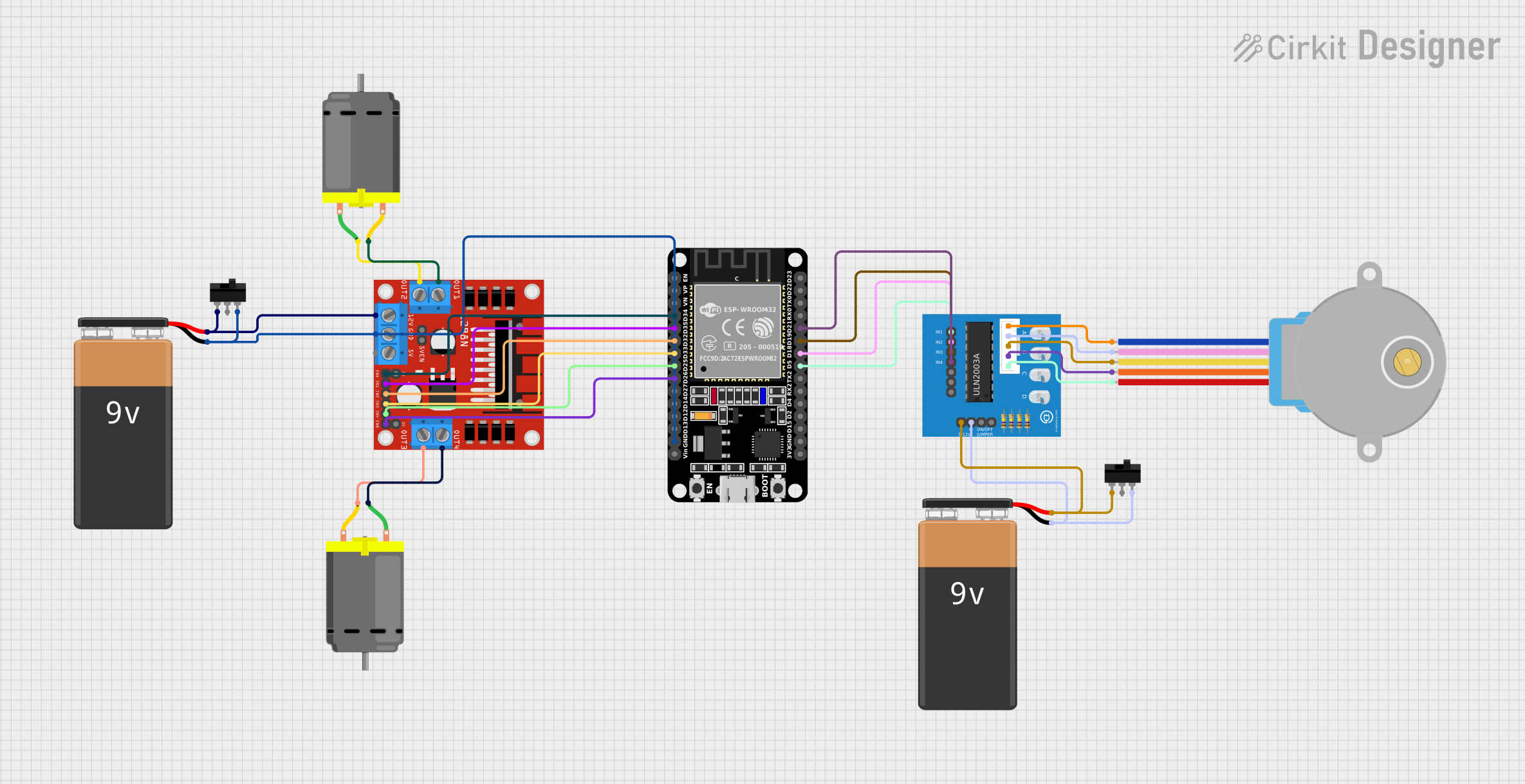


Explore Projects Built with L293 DC and Stepper motro driver
Common Applications:
- Robotics (e.g., motorized robots, robotic arms)
- Automation systems
- Motorized toys
- Conveyor belts
- Stepper motor control for CNC machines or 3D printers
Technical Specifications
Below are the key technical details of the L293 motor driver IC:
| Parameter | Value |
|---|---|
| Operating Voltage | 4.5V to 36V |
| Output Current (per channel) | 600mA (continuous), 1.2A (peak) |
| Logic Input Voltage | 4.5V to 7V |
| Number of Channels | 2 (dual H-bridge) |
| Motor Types Supported | DC motors, stepper motors |
| Enable Pins | 2 (one for each H-bridge) |
| Thermal Shutdown | Yes |
| Package Type | DIP16, SOIC16 |
Pin Configuration and Descriptions
The L293 IC has 16 pins, as described in the table below:
| Pin Number | Pin Name | Description |
|---|---|---|
| 1 | Enable 1,2 | Enables H-bridge 1 (controls motor 1). High = Enabled, Low = Disabled. |
| 2 | Input 1 | Logic input for H-bridge 1. Controls the direction of motor 1. |
| 3 | Output 1 | Output for H-bridge 1. Connect to one terminal of motor 1. |
| 4 | GND | Ground connection. |
| 5 | GND | Ground connection. |
| 6 | Output 2 | Output for H-bridge 1. Connect to the other terminal of motor 1. |
| 7 | Input 2 | Logic input for H-bridge 1. Controls the direction of motor 1. |
| 8 | Vcc2 (Motor) | Supply voltage for motors (4.5V to 36V). |
| 9 | Enable 3,4 | Enables H-bridge 2 (controls motor 2). High = Enabled, Low = Disabled. |
| 10 | Input 3 | Logic input for H-bridge 2. Controls the direction of motor 2. |
| 11 | Output 3 | Output for H-bridge 2. Connect to one terminal of motor 2. |
| 12 | GND | Ground connection. |
| 13 | GND | Ground connection. |
| 14 | Output 4 | Output for H-bridge 2. Connect to the other terminal of motor 2. |
| 15 | Input 4 | Logic input for H-bridge 2. Controls the direction of motor 2. |
| 16 | Vcc1 (Logic) | Supply voltage for logic circuitry (4.5V to 7V). |
Usage Instructions
How to Use the L293 in a Circuit
Power Connections:
- Connect
Vcc1(pin 16) to a 5V power supply for the logic circuitry. - Connect
Vcc2(pin 8) to the motor power supply (4.5V to 36V, depending on the motor). - Connect all
GNDpins (pins 4, 5, 12, 13) to the ground of the power supply.
- Connect
Motor Connections:
- For motor 1, connect its terminals to
Output 1(pin 3) andOutput 2(pin 6). - For motor 2, connect its terminals to
Output 3(pin 11) andOutput 4(pin 14).
- For motor 1, connect its terminals to
Control Logic:
- Use the
Inputpins (2, 7 for motor 1; 10, 15 for motor 2) to control the direction of the motors. - Set the
Enablepins (1 for motor 1; 9 for motor 2) high to enable the respective H-bridge.
- Use the
Direction Control:
- To rotate a motor in one direction, set one
Inputpin high and the other low. - To reverse the direction, swap the logic levels of the
Inputpins.
- To rotate a motor in one direction, set one
Enable/Disable Motors:
- Set the
Enablepin low to disable the motor (outputs will be in high-impedance state).
- Set the
Example: Controlling a DC Motor with Arduino UNO
Below is an example Arduino sketch to control a DC motor using the L293:
// Define L293 pins connected to Arduino
const int enablePin = 9;  // Enable pin for motor 1
const int input1 = 7;     // Input 1 for motor 1
const int input2 = 8;     // Input 2 for motor 1

void setup() {
  // Set pin modes
  pinMode(enablePin, OUTPUT);
  pinMode(input1, OUTPUT);
  pinMode(input2, OUTPUT);

  // Initialize motor in stopped state
  digitalWrite(enablePin, LOW);  // Disable motor
  digitalWrite(input1, LOW);     // Set input1 low
  digitalWrite(input2, LOW);     // Set input2 low
}

void loop() {
  // Rotate motor clockwise
  digitalWrite(enablePin, HIGH);  // Enable motor
  digitalWrite(input1, HIGH);     // Set input1 high
  digitalWrite(input2, LOW);      // Set input2 low
  delay(2000);                    // Run motor for 2 seconds

  // Rotate motor counterclockwise
  digitalWrite(input1, LOW);      // Set input1 low
  digitalWrite(input2, HIGH);     // Set input2 high
  delay(2000);                    // Run motor for 2 seconds

  // Stop motor
  digitalWrite(enablePin, LOW);   // Disable motor
  delay(2000);                    // Wait for 2 seconds
}
Best Practices:
- Use a heat sink if the IC gets too hot during operation.
- Add flyback diodes across the motor terminals to protect the IC from voltage spikes.
- Ensure the motor's current requirements do not exceed the L293's maximum ratings.
Troubleshooting and FAQs
Common Issues and Solutions
Motor Not Spinning:
- Check if the
Enablepin is set high. - Verify the power supply connections to
Vcc1andVcc2. - Ensure the
Inputpins are receiving the correct logic levels.
- Check if the
Motor Spins in Only One Direction:
- Verify the connections to the
Inputpins. - Check if one of the
Inputpins is stuck at a fixed logic level.
- Verify the connections to the
IC Overheating:
- Ensure the motor's current does not exceed 600mA per channel.
- Use a heat sink or cooling fan to dissipate heat.
No Output Voltage on Motor Terminals:
- Confirm that the
Enablepin is high. - Check for loose or incorrect wiring.
- Confirm that the
FAQs
Q: Can the L293 drive stepper motors?
A: Yes, the L293 can drive stepper motors by controlling the sequence of the Input pins. Each H-bridge can control one coil of the stepper motor.
Q: What is the difference between Vcc1 and Vcc2?
A: Vcc1 powers the logic circuitry (4.5V to 7V), while Vcc2 powers the motors (4.5V to 36V).
Q: Can I use the L293 with a 3.3V microcontroller?
A: The L293 requires a minimum logic voltage of 4.5V, so it is not directly compatible with 3.3V logic. Use a level shifter or a 5V microcontroller.
Q: How many motors can the L293 control?
A: The L293 can control two DC motors or one stepper motor.