How to Use mkem0001_LED_module: Examples, Pinouts, and Specs
Introduction
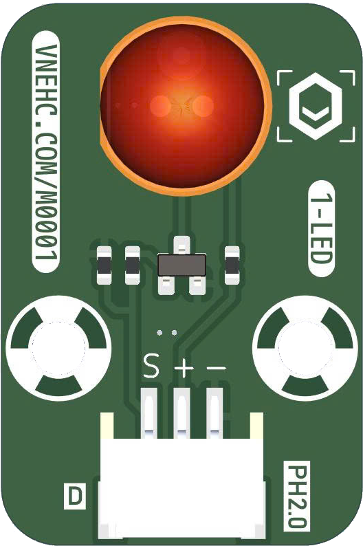
The mkem0001_LED_module is a compact and efficient LED module manufactured by mkevn. Designed for seamless integration into a wide range of electronic projects, this module offers bright illumination while maintaining low power consumption. Its small form factor and ease of use make it ideal for hobbyists, students, and professionals alike.
Explore Projects Built with mkem0001_LED_module
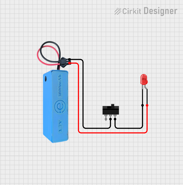
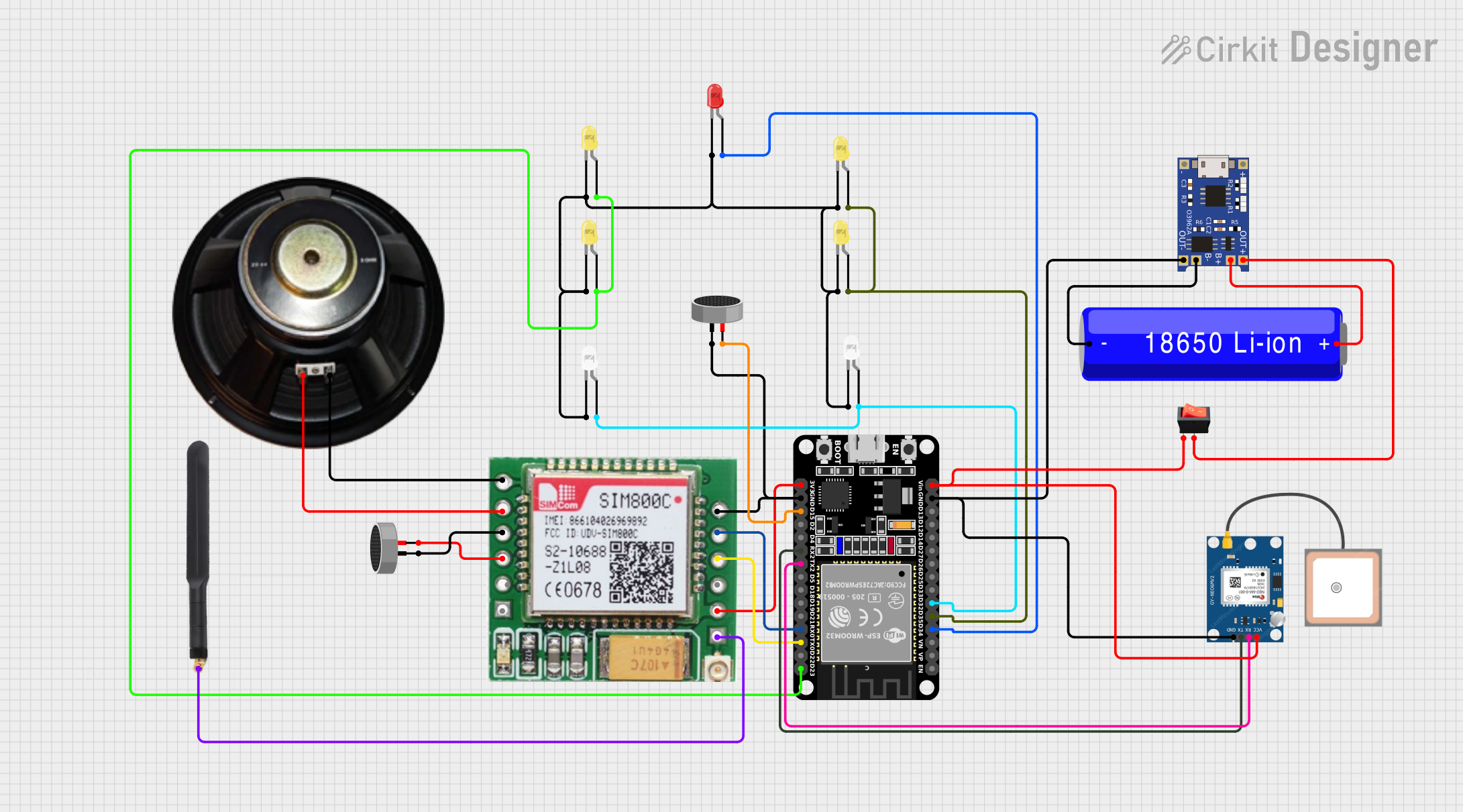
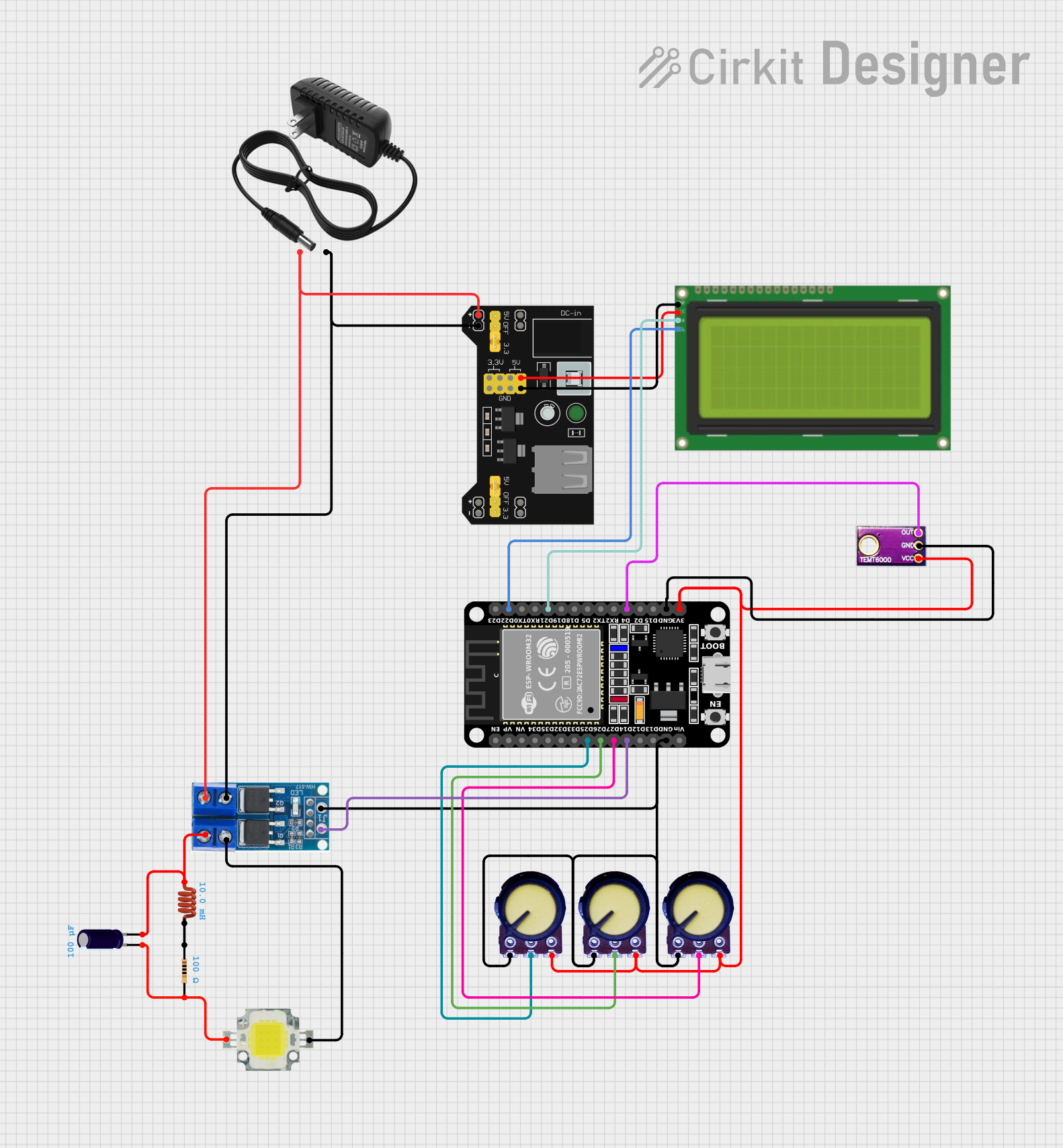

Explore Projects Built with mkem0001_LED_module
Common Applications and Use Cases
- Indicator lights in electronic circuits
- Backlighting for displays and panels
- Decorative lighting in DIY projects
- Status indicators in IoT devices
- Educational projects for learning about LEDs and circuits
Technical Specifications
The mkem0001_LED_module is designed to operate efficiently under standard conditions. Below are its key technical details:
| Parameter | Value |
|---|---|
| Manufacturer | mkevn |
| Part ID | mkem0001 |
| Operating Voltage | 3.0V to 5.0V |
| Operating Current | 20mA (typical) |
| Power Consumption | 0.1W (typical) |
| LED Color | Bright White |
| Luminous Intensity | 1000 mcd (typical) |
| Dimensions | 10mm x 10mm x 3mm |
| Operating Temperature | -20°C to +70°C |
| Connector Type | 2-pin header (male) |
Pin Configuration and Descriptions
The mkem0001_LED_module has a simple 2-pin configuration for easy integration:
| Pin | Name | Description |
|---|---|---|
| 1 | VCC | Positive voltage input (3.0V to 5.0V) |
| 2 | GND | Ground connection |
Usage Instructions
The mkem0001_LED_module is straightforward to use and can be connected directly to a power source or a microcontroller. Follow the steps below to integrate it into your circuit:
Basic Circuit Connection
- Connect the VCC pin of the module to a 3.0V to 5.0V power source.
- Connect the GND pin to the ground of the power source.
- Optionally, include a current-limiting resistor (e.g., 220Ω) in series with the VCC pin to protect the LED from excessive current.
Using with an Arduino UNO
The mkem0001_LED_module can be easily controlled using an Arduino UNO. Below is an example code to blink the LED:
// Example code to blink the mkem0001_LED_module using Arduino UNO

// Define the pin connected to the LED module
const int ledPin = 13; // Connect the VCC pin of the module to pin 13

void setup() {
  pinMode(ledPin, OUTPUT); // Set the LED pin as an output
}

void loop() {
  digitalWrite(ledPin, HIGH); // Turn the LED on
  delay(1000);               // Wait for 1 second
  digitalWrite(ledPin, LOW);  // Turn the LED off
  delay(1000);               // Wait for 1 second
}
Important Considerations and Best Practices
- Always use a current-limiting resistor to prevent damage to the LED.
- Ensure the operating voltage does not exceed 5.0V.
- Avoid exposing the module to temperatures outside the specified range (-20°C to +70°C).
- Handle the module carefully to avoid damaging the pins or the LED.
Troubleshooting and FAQs
Common Issues and Solutions
The LED does not light up:
- Ensure the power supply is within the operating voltage range (3.0V to 5.0V).
- Check the connections to the VCC and GND pins.
- Verify that the current-limiting resistor is not too large, which could reduce the current below the LED's operating threshold.
The LED is dim:
- Confirm that the power supply is providing sufficient voltage.
- Check the value of the current-limiting resistor; a higher resistance value may reduce brightness.
The LED flickers:
- Ensure stable power supply voltage.
- Check for loose or intermittent connections in the circuit.
The LED overheats:
- Verify that the current-limiting resistor is properly sized to limit current to 20mA.
- Ensure the module is not exposed to excessive ambient temperatures.
FAQs
Q: Can I use the mkem0001_LED_module with a 12V power supply?
A: No, the module is designed to operate within a voltage range of 3.0V to 5.0V. Using a higher voltage may damage the LED.
Q: Do I need a resistor if I connect the module to an Arduino?
A: Yes, it is recommended to use a current-limiting resistor (e.g., 220Ω) to protect the LED from excessive current.
Q: Can I use this module outdoors?
A: The module is not waterproof or weatherproof. If you plan to use it outdoors, ensure it is enclosed in a protective, weather-resistant casing.
Q: How long will the LED last?
A: The LED has a typical lifespan of 50,000 hours under normal operating conditions.
By following this documentation, you can effectively integrate and use the mkem0001_LED_module in your projects.