How to Use D1mini stacked with Power Adapter: Examples, Pinouts, and Specs
Introduction
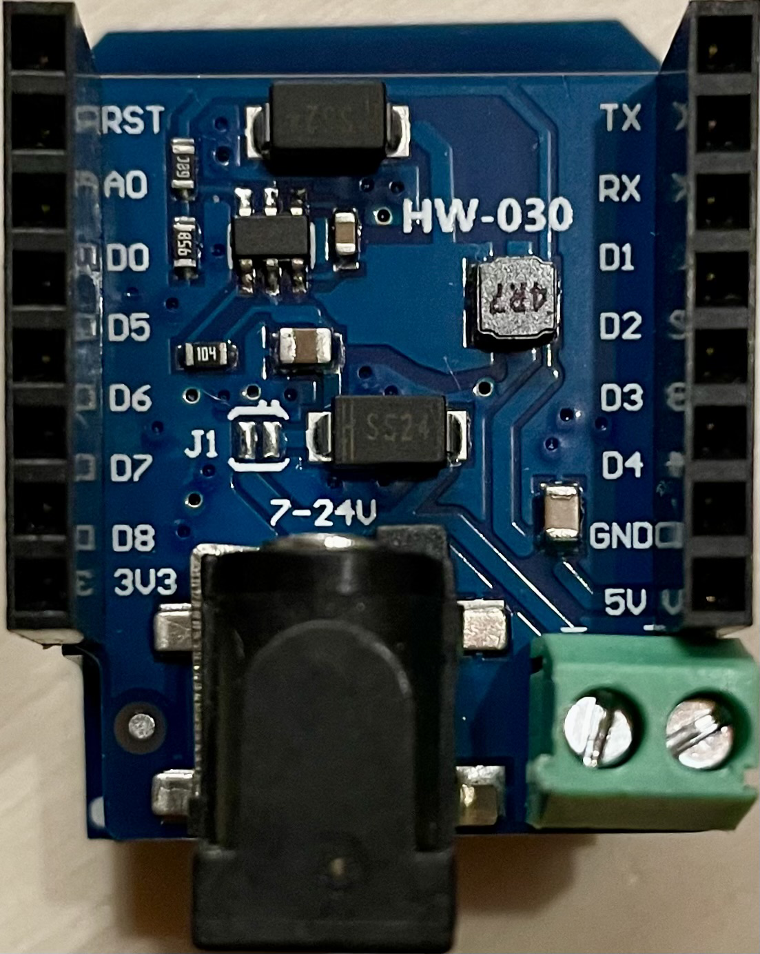
The D1mini with Power Adapter is a compact development board designed by Wemos, which integrates the ESP8266 WiFi module. This board is particularly suitable for Internet of Things (IoT) projects due to its wireless capabilities and ease of use. It can be powered through a micro USB port, which allows for convenient connection to a power adapter or a computer.
Explore Projects Built with D1mini stacked with Power Adapter

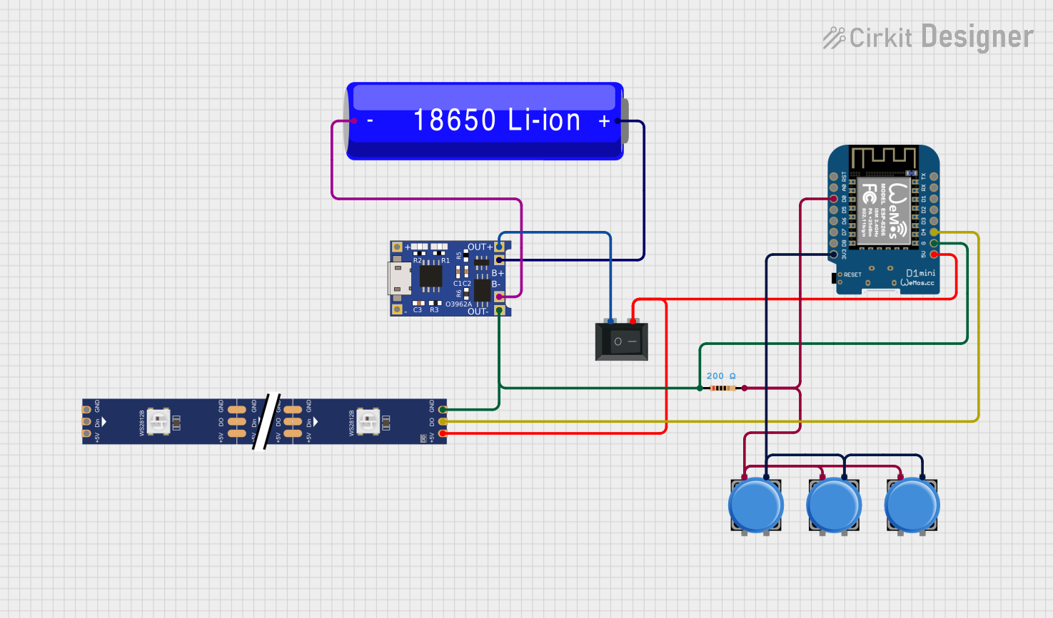
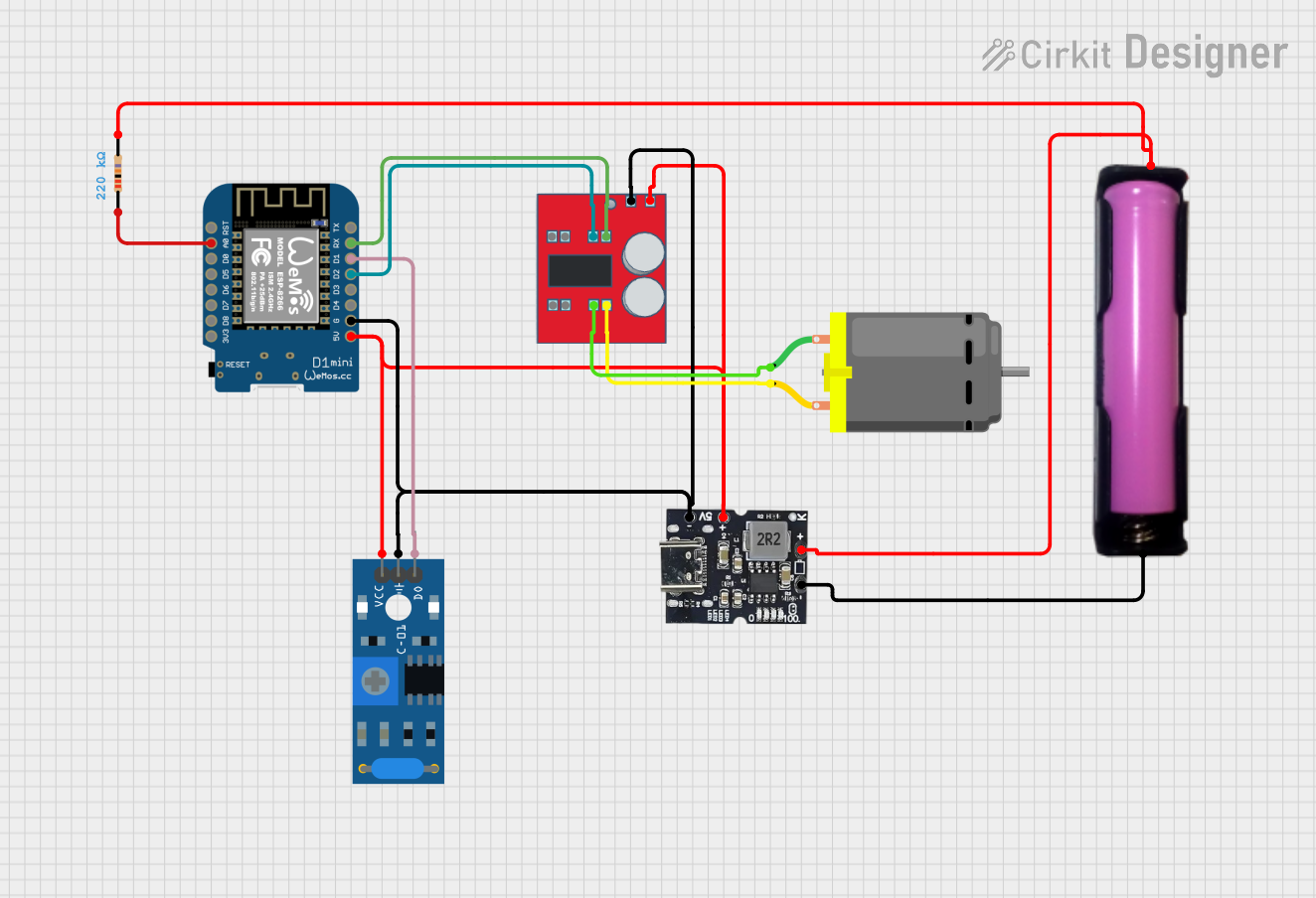

Explore Projects Built with D1mini stacked with Power Adapter
Common Applications and Use Cases
- Smart home devices
- Wireless sensors
- IoT prototypes
- Remote data logging
- DIY electronics projects
Technical Specifications
General Specifications
- Microcontroller: ESP8266
- Operating Voltage: 3.3V
- Digital I/O Pins: 11
- Analog Input Pins: 1 (Max input: 3.2V)
- Clock Speed: 80/160MHz
- Flash Memory: 4MB
- Wireless Standard: 802.11 b/g/n
- Micro USB Port: For power and programming
Pin Configuration and Descriptions
| Pin | Function | Description |
|---|---|---|
| TX | TXD | UART transmit pin, used for serial output |
| RX | RXD | UART receive pin, used for serial input |
| A0 | Analog Input | Analog input, max 3.2V input |
| D0-D8 | GPIO | General Purpose Input/Output pins |
| G | Ground | Ground connection |
| 5V | 5V Input | 5V power input from USB or power adapter |
| 3V3 | 3.3V Output | 3.3V power output to external components |
| RST | Reset | Resets the microcontroller |
Usage Instructions
Connecting the D1mini to a Circuit
- Ensure the power adapter is disconnected before making any connections.
- Connect the D1mini pins to the components of your circuit according to your project's schematic.
- Use the micro USB port to connect the D1mini to a power source or to program the board.
Programming the D1mini
- Install the latest version of the Arduino IDE.
- Install the ESP8266 board package using the Boards Manager in the Arduino IDE.
- Select the correct board (D1mini) and port from the Tools menu.
- Write or load your Arduino sketch (code) into the IDE.
- Click the "Upload" button to program the D1mini.
Important Considerations and Best Practices
- Always verify the power requirements of external components to prevent damage.
- Use a regulated 5V power supply when not using USB power.
- Avoid exposing the board to static electricity or physical stress.
- Ensure proper ventilation to prevent overheating during operation.
Example Code for Arduino UNO
#include <ESP8266WiFi.h>

// Replace with your network credentials
const char* ssid = "your_SSID";
const char* password = "your_PASSWORD";

void setup() {
  Serial.begin(115200);
  // Connect to Wi-Fi
  WiFi.begin(ssid, password);
  while (WiFi.status() != WL_CONNECTED) {
    delay(500);
    Serial.print(".");
  }
  Serial.println("");
  Serial.print("Connected to WiFi network with IP Address: ");
  Serial.println(WiFi.localIP());
}

void loop() {
  // Put your main code here, to run repeatedly:
}
Troubleshooting and FAQs
Common Issues
- D1mini not powering on: Ensure the micro USB cable and power adapter are functioning and properly connected.
- Cannot upload sketches: Check the USB cable, select the correct board and port in the Arduino IDE, and ensure drivers are installed.
- WiFi not connecting: Verify the SSID and password are correct and that the WiFi network is within range.
Solutions and Tips for Troubleshooting
- If the D1mini overheats, disconnect it immediately and check for shorts in your circuit.
- For persistent connectivity issues, try resetting the board or re-flashing the firmware.
- Ensure that the baud rate in the Serial Monitor matches the baud rate specified in your sketch.
FAQs
Q: Can the D1mini be powered by batteries? A: Yes, it can be powered by batteries, but ensure the voltage is regulated to 5V for the USB input or 3.3V if directly supplying the board.
Q: Is the D1mini compatible with all Arduino libraries? A: Most libraries that do not rely on specific hardware features of other Arduino boards should work with the D1mini. Always check the library documentation for compatibility.
Q: How do I reset the D1mini to factory settings? A: You can reset the D1mini by uploading an empty sketch or by using the on-board reset button.
For further assistance, consult the Wemos community forums or the extensive online resources available for the ESP8266.