How to Use multi-turn potentiometer: Examples, Pinouts, and Specs
Introduction
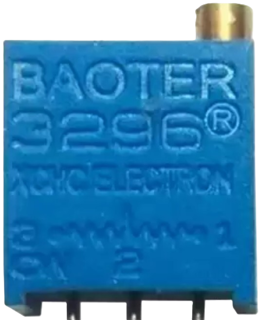
A multi-turn potentiometer is a type of variable resistor designed for precise resistance adjustments. Unlike standard potentiometers, which typically allow for a single rotation of the shaft, multi-turn potentiometers require multiple rotations to traverse their full resistance range. This design enables finer control and higher resolution, making them ideal for applications where precision is critical.
Explore Projects Built with multi-turn potentiometer


Explore Projects Built with multi-turn potentiometer
Common Applications and Use Cases
- Volume Control: Fine-tuning audio levels in amplifiers and audio equipment.
- Tuning Circuits: Adjusting frequency or gain in RF and analog circuits.
- Calibration: Setting precise reference voltages or resistance values in test equipment.
- Industrial Controls: Used in machinery for precise adjustments of parameters.
- Sensor Calibration: Adjusting sensitivity or offset in sensor circuits.
Technical Specifications
Below are the key technical details for the multi-turn potentiometer with manufacturer part ID 1K:
General Specifications
- Manufacturer: Others
- Part ID: 1K
- Resistance Range: 0 Ω to 1 kΩ
- Number of Turns: 10 turns (typical)
- Power Rating: 0.5 W (500 mW)
- Tolerance: ±10%
- Temperature Range: -55°C to +125°C
- Adjustment Type: Screwdriver slot or knob (depending on model)
- Mounting Type: Through-hole or panel mount
Pin Configuration and Descriptions
The multi-turn potentiometer typically has three pins, as described in the table below:
| Pin Number | Name | Description |
|---|---|---|
| 1 | Terminal 1 | One end of the resistive element. Connect to the circuit's voltage source. |
| 2 | Wiper | Adjustable terminal that moves along the resistive element. Provides output. |
| 3 | Terminal 2 | The other end of the resistive element. Connect to ground or circuit load. |
Usage Instructions
How to Use the Component in a Circuit
- Identify the Pins: Locate the three pins (Terminal 1, Wiper, and Terminal 2) on the potentiometer.
- Connect the Circuit:
- Connect Terminal 1 to the positive voltage supply.
- Connect Terminal 2 to ground or the load.
- Connect the Wiper (Pin 2) to the input of the circuit where the variable resistance is required.
- Adjust the Resistance:
- Use a screwdriver or knob to rotate the shaft of the potentiometer.
- Turning the shaft clockwise or counterclockwise will increase or decrease the resistance between the wiper and the terminals.
Important Considerations and Best Practices
- Avoid Overturning: Do not force the shaft beyond its mechanical limits to prevent damage.
- Power Rating: Ensure the power dissipation does not exceed the rated 0.5 W to avoid overheating.
- Stable Mounting: Secure the potentiometer firmly to prevent movement during operation.
- Debouncing: If used in digital circuits, consider adding a capacitor to reduce noise caused by wiper movement.
- Arduino Compatibility: The potentiometer can be used with microcontrollers like Arduino for analog input.
Example: Connecting to an Arduino UNO
The following example demonstrates how to use a multi-turn potentiometer to control the brightness of an LED using an Arduino UNO.
// Define pin connections
const int potPin = A0;  // Potentiometer wiper connected to analog pin A0
const int ledPin = 9;   // LED connected to digital pin 9 (PWM capable)

void setup() {
  pinMode(ledPin, OUTPUT);  // Set LED pin as output
}

void loop() {
  int potValue = analogRead(potPin);  // Read potentiometer value (0-1023)

  // Map the potentiometer value to a PWM range (0-255)
  int ledBrightness = map(potValue, 0, 1023, 0, 255);

  analogWrite(ledPin, ledBrightness);  // Set LED brightness
}
Notes:
- Ensure the potentiometer's wiper is connected to the analog input pin (A0 in this case).
- The LED brightness will vary smoothly as the potentiometer is adjusted.
Troubleshooting and FAQs
Common Issues and Solutions
No Change in Resistance:
- Cause: The potentiometer may be damaged or improperly connected.
- Solution: Verify the connections and ensure the potentiometer is functional.
Erratic Output:
- Cause: Dust or debris inside the potentiometer or poor contact with the wiper.
- Solution: Clean the potentiometer or replace it if necessary.
Overheating:
- Cause: Exceeding the power rating of the potentiometer.
- Solution: Reduce the current or voltage applied to the potentiometer.
Limited Adjustment Range:
- Cause: Incorrect wiring or using a potentiometer with an unsuitable resistance range.
- Solution: Check the wiring and ensure the resistance range matches the application.
FAQs
Q1: Can I use a multi-turn potentiometer for high-current applications?
A1: No, multi-turn potentiometers are designed for low-current applications. Use a power resistor or other suitable component for high-current circuits.
Q2: How do I know when the potentiometer has reached its limit?
A2: You will feel a mechanical stop when the shaft reaches the end of its range. Do not force it beyond this point.
Q3: Can I use this potentiometer to measure resistance directly?
A3: Yes, you can measure the resistance between the wiper and the terminals using a multimeter.
Q4: What is the advantage of a multi-turn potentiometer over a single-turn one?
A4: Multi-turn potentiometers provide finer control and higher resolution, making them ideal for precision applications.