How to Use Terminal PCB 2 Pin: Examples, Pinouts, and Specs
Introduction
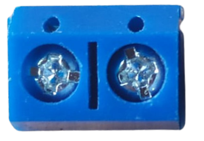
A Terminal PCB 2 Pin, also known as a 2-pin terminal block or screw terminal, is a type of electrical connector used to secure two wires to a printed circuit board (PCB). This component is widely used in electronics for creating a secure and removable connection, making it ideal for applications where wiring may need to be frequently changed or maintained.
Explore Projects Built with Terminal PCB 2 Pin


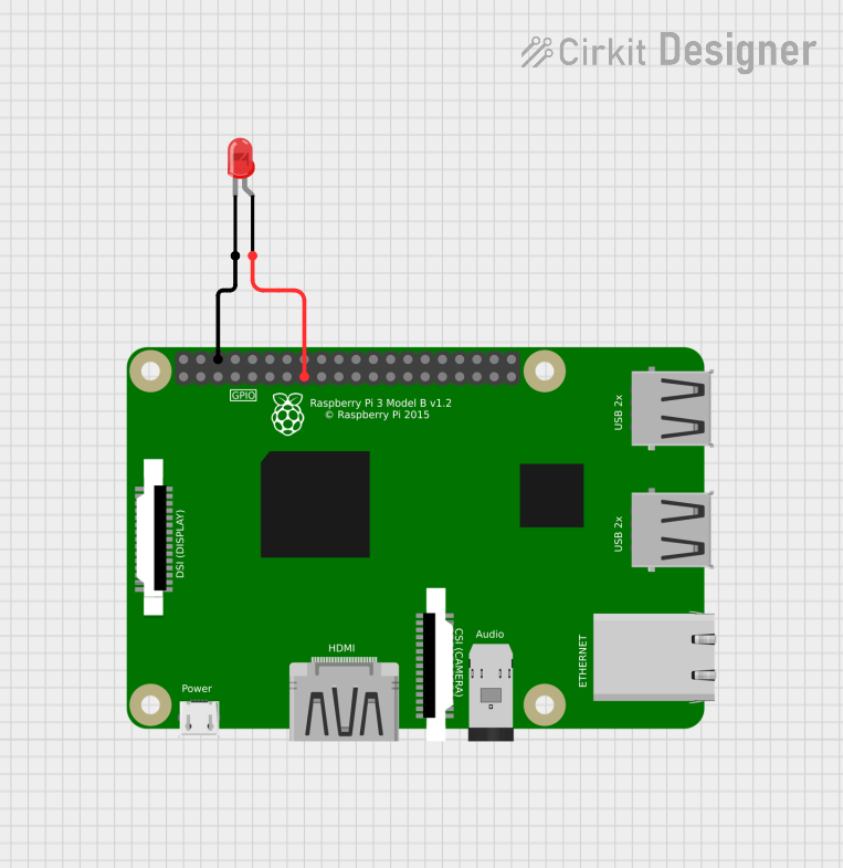

Explore Projects Built with Terminal PCB 2 Pin
Common Applications and Use Cases
- Prototyping electronic circuits
- Industrial control systems
- Consumer electronics
- Power supply connections
- Speaker connections in audio systems
Technical Specifications
Key Technical Details
- Rated Voltage: Typically ranges from 250V to 300V
- Rated Current: Usually up to 10A
- Wire Size: Often accepts 22-14 AWG wires
- Pitch: Commonly 5.08mm (distance between the centers of each pin)
- Torque: Recommended screw tightening torque is usually around 0.2Nm to 0.5Nm
Pin Configuration and Descriptions
| Pin Number | Description |
|---|---|
| 1 | Connection point for the first wire or cable |
| 2 | Connection point for the second wire or cable |
Usage Instructions
How to Use the Component in a Circuit
- Wire Stripping: Strip approximately 5-7mm of insulation from the end of the wire to be connected.
- Insertion: Loosen the screws on the terminal block, insert the stripped wire ends into the corresponding holes above the terminal screws.
- Securing Wires: Tighten the screws to clamp the wires in place. Ensure a snug fit without over-tightening to avoid damaging the wire.
- PCB Mounting: Align the pins of the terminal block with the designated holes on the PCB and solder them in place.
Important Considerations and Best Practices
- Wire Gauge Compatibility: Ensure the wire gauge is compatible with the terminal block's specifications.
- Soldering: Use proper soldering techniques to avoid cold joints or damage to the PCB.
- Inspection: After installation, inspect the connections to ensure they are secure and there is no risk of short circuits.
- Maintenance: Periodically check and retighten the screws if necessary to maintain a good connection.
Troubleshooting and FAQs
Common Issues Users Might Face
- Loose Connections: Wires may become loose over time due to vibration or thermal expansion.
- Over-Tightening: Excessive force when tightening screws can strip the threads or damage the wire.
- Corrosion: Terminals can corrode in harsh environments, leading to poor connections.
Solutions and Tips for Troubleshooting
- Regular Inspection: Periodically check the tightness of the screws and the integrity of the wire connections.
- Proper Torque: Use a torque screwdriver if available to apply the correct torque.
- Environmental Protection: Use appropriate enclosures to protect the terminal block from harsh environments.
FAQs
Q: Can I use a Terminal PCB 2 Pin with any wire gauge? A: No, you must use a wire gauge that is compatible with the terminal block's specifications.
Q: How do I know if I've tightened the screws enough? A: The wire should be held firmly in place without being able to be pulled out easily. Do not over-tighten as this may damage the wire or terminal.
Q: Is soldering required to mount the Terminal PCB 2 Pin to a PCB? A: Yes, soldering is required to create a permanent and stable connection to the PCB.
Example Code for Arduino UNO Connection
// Example code to demonstrate how to use a Terminal PCB 2 Pin with an Arduino UNO
// This example assumes the Terminal PCB 2 Pin is used to connect an LED.

int ledPin = 13; // LED connected to digital pin 13 through Terminal PCB 2 Pin

void setup() {
  pinMode(ledPin, OUTPUT); // Initialize the digital pin as an output
}

void loop() {
  digitalWrite(ledPin, HIGH); // Turn the LED on
  delay(1000);                // Wait for a second
  digitalWrite(ledPin, LOW);  // Turn the LED off
  delay(1000);                // Wait for a second
}
Note: The above code is a simple blink example. The Terminal PCB 2 Pin is used to connect the LED's positive lead to pin 13 and the negative lead to a ground pin on the Arduino UNO. Ensure that the LED's current and voltage ratings are compatible with the Arduino's output.