Cirkit Designer Logo
Cirkit Designer
Your all-in-one circuit design IDE
Home / 
Component Documentation

How to Use KY-024 Sensor de Campo Magnético : Examples, Pinouts, and Specs

Image of KY-024 Sensor de Campo Magnético
Cirkit Designer LogoDesign with KY-024 Sensor de Campo Magnético in Cirkit Designer

Introduction

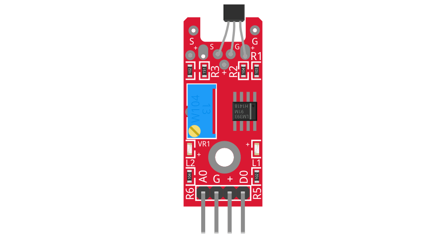
The KY-024 Magnetic Field Sensor, manufactured by Arduino (Part ID: MM), is a versatile component designed to detect the presence and strength of magnetic fields. It outputs an analog voltage proportional to the detected magnetic field strength and includes a digital output for threshold-based detection. This sensor is widely used in applications such as compass systems, magnetic field detection, proximity sensing, and robotics.

Explore Projects Built with KY-024 Sensor de Campo Magnético

Use Cirkit Designer to design, explore, and prototype these projects online. Some projects support real-time simulation. Click "Open Project" to start designing instantly!
ESP32-Based Security System with RFID and Laser Tripwire
Image of CPE doorlock system: A project utilizing KY-024 Sensor de Campo Magnético  in a practical application
This circuit is designed for a comprehensive security and access control system with motion detection, access via RFID, and a break-beam sensor. It includes a solenoid lock controlled by a relay, visual and audible alerts, and a robust power management system with solar and battery backup to ensure uninterrupted operation.
Cirkit Designer LogoOpen Project in Cirkit Designer
Arduino and ESP8266 Nodemcu Controlled Environment Monitoring System with Solar Charging
Image of SOLARM: A project utilizing KY-024 Sensor de Campo Magnético  in a practical application
This circuit is designed for environmental monitoring and response, featuring sensors for temperature, humidity, distance, and soil moisture, with actuation through a servomotor and audio feedback. It is powered by a solar-charged battery system, indicating outdoor or remote deployment with renewable energy utilization.
Cirkit Designer LogoOpen Project in Cirkit Designer
Arduino UNO-Based Battery-Powered Robotic System with Ultrasonic Sensors and Magnetometer
Image of Autonomous Mobile robot v1: A project utilizing KY-024 Sensor de Campo Magnético  in a practical application
This circuit is a sensor-based robotic system controlled by an Arduino UNO. It includes three HC-SR04 ultrasonic sensors for distance measurement, a QMC5883L magnetometer for orientation detection, and an L298N motor driver to control two DC motors, all powered by a Li-ion 18650 battery.
Cirkit Designer LogoOpen Project in Cirkit Designer
Nucleo-L4R5ZI and RM-3100 Magnetometer Sensor Interface
Image of Nucleo-L4R5ZI with rm3100: A project utilizing KY-024 Sensor de Campo Magnético  in a practical application
This circuit integrates a Nucleo-L4R5ZI microcontroller with an RM-3100 magnetometer sensor for magnetic field measurement. Communication between the microcontroller and the sensor is established through I2C protocol, with an additional data ready signal connected to the microcontroller's D9 pin. Power supply and ground connections are established to power the sensor and provide common reference points.
Cirkit Designer LogoOpen Project in Cirkit Designer

Explore Projects Built with KY-024 Sensor de Campo Magnético

Use Cirkit Designer to design, explore, and prototype these projects online. Some projects support real-time simulation. Click "Open Project" to start designing instantly!
Image of CPE doorlock system: A project utilizing KY-024 Sensor de Campo Magnético  in a practical application
ESP32-Based Security System with RFID and Laser Tripwire
This circuit is designed for a comprehensive security and access control system with motion detection, access via RFID, and a break-beam sensor. It includes a solenoid lock controlled by a relay, visual and audible alerts, and a robust power management system with solar and battery backup to ensure uninterrupted operation.
Cirkit Designer LogoOpen Project in Cirkit Designer
Image of SOLARM: A project utilizing KY-024 Sensor de Campo Magnético  in a practical application
Arduino and ESP8266 Nodemcu Controlled Environment Monitoring System with Solar Charging
This circuit is designed for environmental monitoring and response, featuring sensors for temperature, humidity, distance, and soil moisture, with actuation through a servomotor and audio feedback. It is powered by a solar-charged battery system, indicating outdoor or remote deployment with renewable energy utilization.
Cirkit Designer LogoOpen Project in Cirkit Designer
Image of Autonomous Mobile robot v1: A project utilizing KY-024 Sensor de Campo Magnético  in a practical application
Arduino UNO-Based Battery-Powered Robotic System with Ultrasonic Sensors and Magnetometer
This circuit is a sensor-based robotic system controlled by an Arduino UNO. It includes three HC-SR04 ultrasonic sensors for distance measurement, a QMC5883L magnetometer for orientation detection, and an L298N motor driver to control two DC motors, all powered by a Li-ion 18650 battery.
Cirkit Designer LogoOpen Project in Cirkit Designer
Image of Nucleo-L4R5ZI with rm3100: A project utilizing KY-024 Sensor de Campo Magnético  in a practical application
Nucleo-L4R5ZI and RM-3100 Magnetometer Sensor Interface
This circuit integrates a Nucleo-L4R5ZI microcontroller with an RM-3100 magnetometer sensor for magnetic field measurement. Communication between the microcontroller and the sensor is established through I2C protocol, with an additional data ready signal connected to the microcontroller's D9 pin. Power supply and ground connections are established to power the sensor and provide common reference points.
Cirkit Designer LogoOpen Project in Cirkit Designer

Technical Specifications

The KY-024 sensor combines a linear Hall-effect sensor and a potentiometer for sensitivity adjustment. Below are its key technical details:

Key Specifications

  • Operating Voltage: 3.3V to 5V DC
  • Output Types:
    • Analog output (proportional to magnetic field strength)
    • Digital output (high/low based on threshold)
  • Sensitivity Adjustment: Via onboard potentiometer
  • Dimensions: 32mm x 14mm x 8mm
  • Operating Temperature: -40°C to 85°C
  • Manufacturer Part ID: MM

Pin Configuration and Descriptions

The KY-024 sensor has a 3-pin interface for easy integration into circuits. Below is the pinout:

Pin Name Description
1 VCC Power supply input (3.3V to 5V DC)
2 GND Ground connection
3 DO Digital output (high/low signal based on magnetic field threshold)
4 AO Analog output (voltage proportional to magnetic field strength)

Usage Instructions

The KY-024 sensor is straightforward to use in a variety of circuits. Below are the steps and considerations for proper usage:

Connecting the KY-024 to an Arduino UNO

  1. Wiring:

    • Connect the VCC pin of the KY-024 to the 5V pin on the Arduino UNO.
    • Connect the GND pin of the KY-024 to the GND pin on the Arduino UNO.
    • Connect the AO pin of the KY-024 to an analog input pin (e.g., A0) on the Arduino UNO.
    • Optionally, connect the DO pin to a digital input pin (e.g., D2) for threshold-based detection.
  2. Adjusting Sensitivity:

    • Use the onboard potentiometer to adjust the sensitivity of the digital output. Turning the potentiometer clockwise increases sensitivity, while turning it counterclockwise decreases sensitivity.
  3. Arduino Code Example: Below is an example Arduino sketch to read both the analog and digital outputs of the KY-024 sensor:

    // KY-024 Magnetic Field Sensor Example
    // Reads analog and digital outputs and prints them to the Serial Monitor
    
    const int analogPin = A0; // Pin connected to AO (Analog Output)
    const int digitalPin = 2; // Pin connected to DO (Digital Output)
    
    void setup() {
      Serial.begin(9600); // Initialize serial communication at 9600 baud
      pinMode(digitalPin, INPUT); // Set digital pin as input
    }
    
    void loop() {
      int analogValue = analogRead(analogPin); // Read analog value
      int digitalValue = digitalRead(digitalPin); // Read digital value
    
      // Print the values to the Serial Monitor
      Serial.print("Analog Value: ");
      Serial.print(analogValue);
      Serial.print(" | Digital Value: ");
      Serial.println(digitalValue);
    
      delay(500); // Wait for 500ms before the next reading
    }
    

Best Practices

  • Ensure the sensor is powered within its operating voltage range (3.3V to 5V DC).
  • Avoid placing the sensor near strong electromagnetic interference sources, as this may affect accuracy.
  • Use the analog output for precise magnetic field strength measurements and the digital output for simple threshold-based detection.
  • Calibrate the sensor using the potentiometer to suit your specific application.

Troubleshooting and FAQs

Common Issues and Solutions

  1. No Output from the Sensor:

    • Cause: Incorrect wiring or insufficient power supply.
    • Solution: Double-check the connections and ensure the sensor is powered with 3.3V to 5V DC.
  2. Analog Output is Constant:

    • Cause: The sensor is not exposed to a magnetic field or the field is too weak.
    • Solution: Test the sensor with a stronger magnet or adjust the potentiometer for higher sensitivity.
  3. Digital Output Always High or Low:

    • Cause: Incorrect threshold setting on the potentiometer.
    • Solution: Rotate the potentiometer to adjust the threshold level.
  4. Fluctuating Readings:

    • Cause: Electromagnetic interference or unstable power supply.
    • Solution: Place the sensor away from interference sources and use a decoupling capacitor on the power supply.

FAQs

Q1: Can the KY-024 detect the polarity of a magnetic field?
A1: No, the KY-024 cannot detect the polarity of a magnetic field. It only measures the strength of the field.

Q2: What is the range of magnetic field strength the KY-024 can detect?
A2: The exact range depends on the Hall-effect sensor used, but it is typically suitable for detecting small to moderate magnetic fields.

Q3: Can I use the KY-024 with a 3.3V microcontroller?
A3: Yes, the KY-024 is compatible with 3.3V systems, but ensure the output voltage levels are within the microcontroller's input range.

Q4: How do I know if the sensor is working?
A4: Use a multimeter to measure the voltage on the AO pin. The voltage should vary when a magnet is brought near the sensor.

By following this documentation, you can effectively integrate and troubleshoot the KY-024 Magnetic Field Sensor in your projects.