How to Use PowerBoost 1000 Basic Pad Pad: Examples, Pinouts, and Specs
Introduction
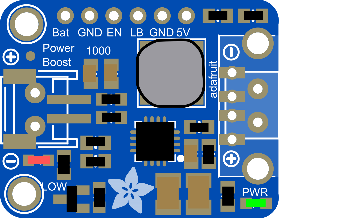
The PowerBoost 1000 Basic Pad Pad is a versatile and compact power supply module designed to step up the voltage to a regulated 5V output capable of supplying up to 1A of current. This component is ideal for portable electronics, wearables, and any application where a stable 5V power source is required from a lower voltage battery, such as a single-cell LiPo (Lithium Polymer) battery. The pad version of this component is particularly suitable for embedding into custom PCB designs, providing a convenient power solution without the need for bulky external modules.
Explore Projects Built with PowerBoost 1000 Basic Pad Pad

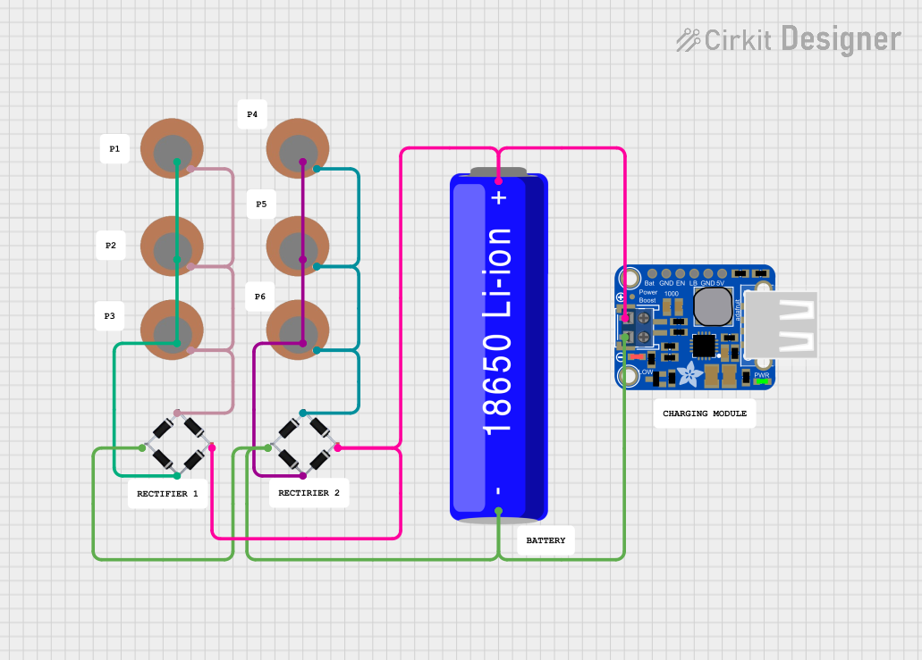
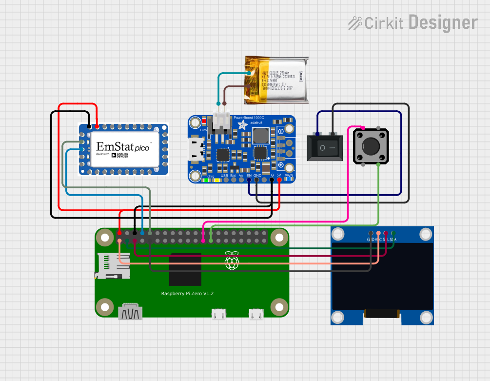
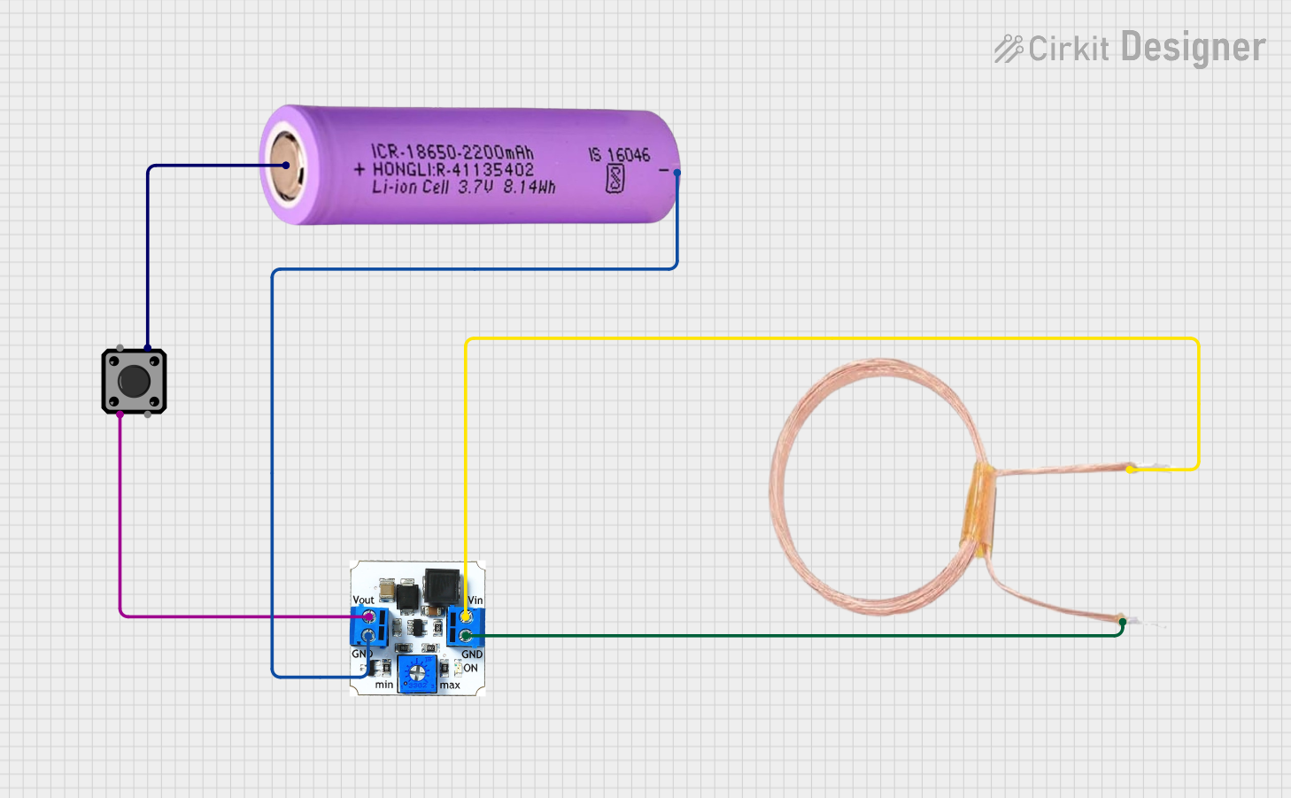
Explore Projects Built with PowerBoost 1000 Basic Pad Pad
Common Applications and Use Cases
- Portable USB chargers
- Battery-powered electronics
- Wearable devices
- DIY electronics projects
- Arduino-based systems
Technical Specifications
Key Technical Details
- Input Voltage: 1.8V to 5.5V
- Output Voltage: 5V regulated
- Output Current: Up to 1A
- Efficiency: Up to 90%
- Quiescent Current: <5mA
- Switching Frequency: 1MHz
- Integrated over-temperature and over-current protection
Pin Configuration and Descriptions
| Pin Name | Description |
|---|---|
| VIN | Input voltage (1.8V to 5.5V) |
| GND | Ground connection |
| 5V | Regulated 5V output |
| EN | Enable pin (active high) |
| BAT | Battery connection for monitoring |
Usage Instructions
How to Use the Component in a Circuit
- Connect the positive terminal of your power source (e.g., LiPo battery) to the VIN pin.
- Connect the negative terminal of your power source to the GND pin.
- The 5V pin will provide a regulated 5V output when the module is enabled.
- The EN pin can be left unconnected for always-on operation or connected to a logic high signal to enable the module.
- The BAT pin can be connected to the positive terminal of the battery if battery monitoring is required.
Important Considerations and Best Practices
- Ensure that the input voltage does not exceed 5.5V to prevent damage to the module.
- Do not exceed the maximum output current of 1A to maintain optimal performance and reliability.
- Provide adequate cooling if the module is expected to operate near its maximum output current for extended periods.
- Keep the power paths as short as possible to minimize losses and improve efficiency.
- Use a multimeter to verify connections and output voltage before connecting sensitive electronics.
Troubleshooting and FAQs
Common Issues Users Might Face
- No Output Voltage: Ensure that the input voltage is within the specified range and that the EN pin is either unconnected or driven high.
- Output Voltage Drops Under Load: This may indicate that the input power source is unable to supply sufficient current. Check the power source and wiring.
- Module Overheating: Reduce the load or improve cooling. Ensure that the input voltage is not too low, as this can cause the module to work harder and generate more heat.
Solutions and Tips for Troubleshooting
- Verify that all connections are secure and free from shorts.
- Measure the input voltage to ensure it falls within the specified range.
- If using the EN pin, ensure it is being driven to a logic high level to enable the module.
- Check for signs of physical damage or overheating on the module.
FAQs
Q: Can I use the PowerBoost 1000 Basic with a 3.7V LiPo battery? A: Yes, the PowerBoost 1000 Basic is designed to work with a single-cell LiPo battery, which typically has a nominal voltage of 3.7V.
Q: Is it possible to charge the battery while providing power to a load? A: The PowerBoost 1000 Basic does not include charging circuitry. For charging capabilities, consider using a version of the PowerBoost that includes a charge controller.
Q: What is the maximum input voltage for the PowerBoost 1000 Basic? A: The maximum input voltage is 5.5V. Exceeding this voltage can damage the module.
Q: How do I integrate the PowerBoost 1000 Basic into my PCB design? A: The pad version of the PowerBoost 1000 Basic is designed for direct soldering onto a PCB. Ensure that the layout follows the recommended footprint and that the power traces can handle the current requirements.
Q: Can I use the PowerBoost 1000 Basic to power an Arduino UNO? A: Yes, the PowerBoost 1000 Basic can be used to power an Arduino UNO or any other microcontroller that requires a 5V supply, as long as the current requirements do not exceed 1A.
Example Arduino UNO Connection
// No specific code is required for basic operation of the PowerBoost 1000 Basic.
// However, if you wish to control the EN pin via an Arduino, you can use the following example.

const int enablePin = 7; // Connect the EN pin of PowerBoost to digital pin 7 on Arduino

void setup() {
  pinMode(enablePin, OUTPUT); // Set the enable pin as an output
  digitalWrite(enablePin, HIGH); // Enable the PowerBoost 1000 Basic
}

void loop() {
  // Your code here. The PowerBoost 1000 Basic will continue to provide power as long as the EN pin is high.
  // To disable power, set the EN pin to LOW:
  // digitalWrite(enablePin, LOW);
}
Remember to keep code comments concise and within the 80 character line length limit.