
How to Use W5500 Mini: Examples, Pinouts, and Specs
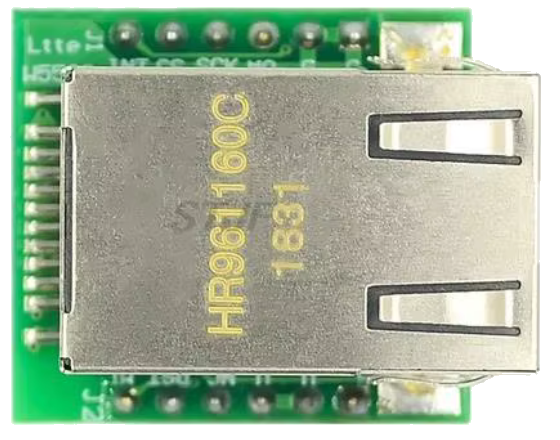
 Design with W5500 Mini in Cirkit Designer
Introduction
The W5500 Mini is a compact Ethernet controller designed to simplify the process of connecting microcontrollers to the internet. It features an integrated TCP/IP stack, which reduces the complexity of implementing network communication in embedded systems. The W5500 Mini is widely used in Internet of Things (IoT) applications, home automation, industrial control systems, and other projects requiring reliable Ethernet connectivity.
Explore Projects Built with W5500 Mini
 Open Project in Cirkit Designer
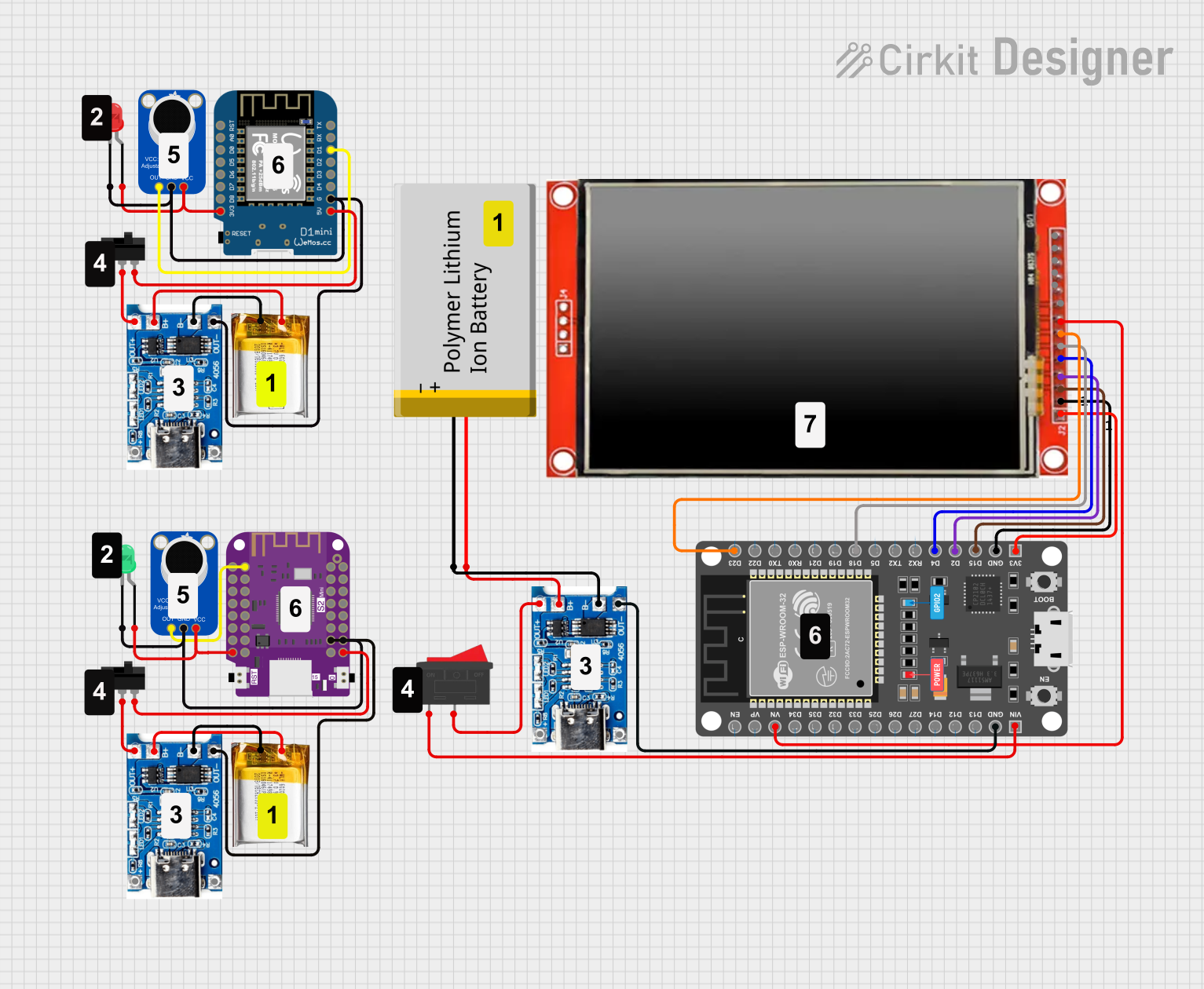 Open Project in Cirkit Designer
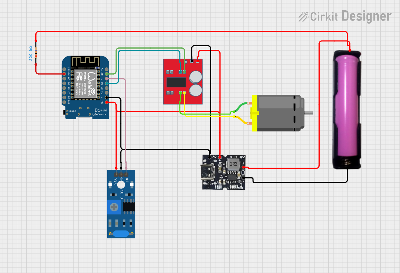 Open Project in Cirkit Designer
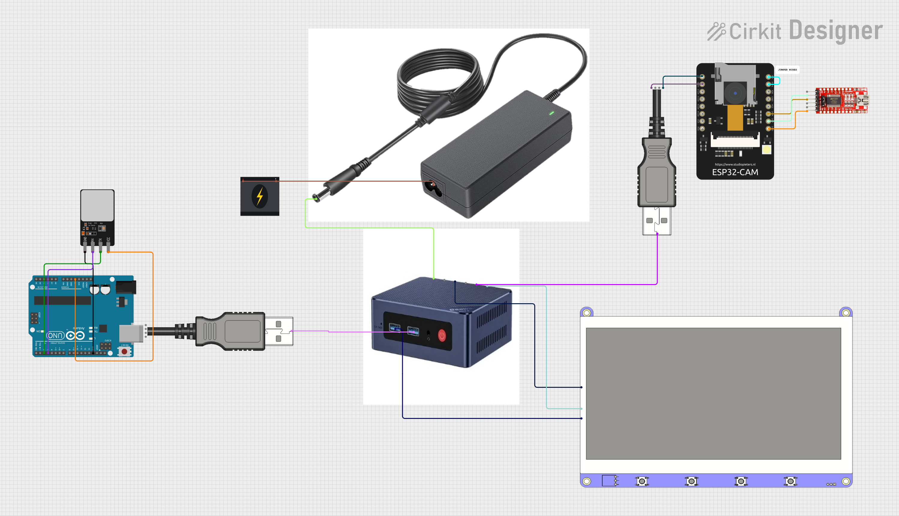 Open Project in Cirkit Designer
Explore Projects Built with W5500 Mini
Open Project in Cirkit DesignerOpen Project in Cirkit DesignerOpen Project in Cirkit DesignerOpen Project in Cirkit DesignerCommon Applications
- IoT devices and smart home systems
- Industrial automation and monitoring
- Data logging and remote control
- Network-enabled embedded systems
- Educational projects and prototyping
Technical Specifications
Key Technical Details
- Manufacturer: W5500 Mini
- Ethernet Standard: IEEE 802.3 10/100 Mbps
- Interface: SPI (Serial Peripheral Interface)
- Operating Voltage: 3.3V (logic level)
- Power Consumption: ~132 mA (typical)
- Integrated Features:
- Built-in TCP/IP stack
- 8 independent sockets for simultaneous connections
- Auto-negotiation for 10/100 Mbps Ethernet
- Operating Temperature: -40°C to +85°C
- Dimensions: Compact form factor for easy integration
Pin Configuration and Descriptions
The W5500 Mini has a standard pinout for SPI communication and power connections. Below is the pin configuration:
| Pin | Name | Description |
|---|---|---|
| 1 | GND | Ground connection |
| 2 | 3.3V | Power supply input (3.3V) |
| 3 | MISO | SPI Master-In-Slave-Out (data output from W5500 to microcontroller) |
| 4 | MOSI | SPI Master-Out-Slave-In (data input from microcontroller to W5500) |
| 5 | SCK | SPI Clock (synchronization signal for SPI communication) |
| 6 | CS | Chip Select (active low, used to enable SPI communication with the W5500) |
| 7 | INT | Interrupt output (used to signal events such as received data) |
| 8 | RST | Reset input (active low, used to reset the W5500) |
Usage Instructions
How to Use the W5500 Mini in a Circuit
- Power Supply: Connect the 3.3V pin to a regulated 3.3V power source and the GND pin to the ground.
- SPI Communication: Connect the SPI pins (MISO, MOSI, SCK, and CS) to the corresponding SPI pins on your microcontroller.
- Interrupt Pin (Optional): Use the INT pin to handle events like incoming data or connection status changes.
- Reset Pin: Connect the RST pin to a GPIO pin on your microcontroller or a manual reset button.
- Ethernet Connection: Plug an Ethernet cable into the RJ45 connector on the W5500 Mini.
Important Considerations
- Ensure the microcontroller operates at 3.3V logic levels. If your microcontroller uses 5V logic, use a level shifter to avoid damaging the W5500 Mini.
- Use a stable and regulated 3.3V power supply to prevent communication errors.
- Properly terminate unused pins to avoid noise or interference.
Example Code for Arduino UNO
Below is an example of how to use the W5500 Mini with an Arduino UNO to establish a basic Ethernet connection:
#include <SPI.h>
#include <Ethernet.h>

// MAC address for the Ethernet shield
byte mac[] = { 0xDE, 0xAD, 0xBE, 0xEF, 0xFE, 0xED };

// IP address for the device (adjust as needed)
IPAddress ip(192, 168, 1, 177);

// Initialize the Ethernet server on port 80
EthernetServer server(80);

void setup() {
  // Start the serial communication for debugging
  Serial.begin(9600);

  // Initialize the Ethernet connection
  if (Ethernet.begin(mac) == 0) {
    Serial.println("Failed to configure Ethernet using DHCP");
    // Manually configure the IP address if DHCP fails
    Ethernet.begin(mac, ip);
  }

  // Start the server
  server.begin();
  Serial.print("Server is at ");
  Serial.println(Ethernet.localIP());
}

void loop() {
  // Listen for incoming clients
  EthernetClient client = server.available();
  if (client) {
    Serial.println("New client connected");
    // Wait until the client sends data
    while (client.connected()) {
      if (client.available()) {
        char c = client.read();
        Serial.write(c); // Echo the received data to the serial monitor

        // Respond to the client
        client.println("HTTP/1.1 200 OK");
        client.println("Content-Type: text/html");
        client.println("Connection: close");
        client.println();
        client.println("<!DOCTYPE HTML>");
        client.println("<html>");
        client.println("<h1>Hello from W5500 Mini!</h1>");
        client.println("</html>");
        break;
      }
    }
    // Close the connection
    client.stop();
    Serial.println("Client disconnected");
  }
}
Notes:
- Replace the
macandipvariables with values appropriate for your network. - Ensure the Ethernet library is installed in your Arduino IDE.
Troubleshooting and FAQs
Common Issues and Solutions
No Ethernet Connection:
- Verify the Ethernet cable is securely connected to the W5500 Mini and the router/switch.
- Check the power supply and ensure it provides a stable 3.3V.
SPI Communication Fails:
- Ensure the SPI pins are correctly connected to the microcontroller.
- Verify the Chip Select (CS) pin is properly configured in your code.
Device Not Responding:
- Check the RST pin connection. If necessary, manually reset the W5500 Mini.
- Ensure the microcontroller logic levels are compatible with the W5500 Mini.
DHCP Fails:
- Verify the router supports DHCP and has available IP addresses.
- Use a static IP address if DHCP is not working.
FAQs
Q: Can the W5500 Mini work with 5V microcontrollers?
A: Yes, but you must use a level shifter to convert the 5V logic levels to 3.3V to avoid damaging the W5500 Mini.
Q: How many simultaneous connections can the W5500 Mini handle?
A: The W5500 Mini supports up to 8 independent sockets for simultaneous connections.
Q: Is the W5500 Mini compatible with other microcontrollers besides Arduino?
A: Yes, the W5500 Mini can be used with any microcontroller that supports SPI communication, such as ESP32, STM32, and Raspberry Pi.
Q: Can I use the W5500 Mini for UDP communication?
A: Yes, the W5500 Mini supports both TCP and UDP protocols.
This concludes the documentation for the W5500 Mini.