How to Use 5 channel IR array: Examples, Pinouts, and Specs
5 Channel Infrared (IR) Array Documentation
1. Introduction
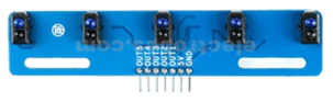
The 5 Channel Infrared (IR) Array is a compact and versatile sensor module that consists of five individual IR sensors arranged in a linear configuration. Each sensor detects infrared signals, making the array ideal for applications requiring multi-point detection. This component is widely used in robotics, automation, and object detection systems.
Common Applications:
- Line Following Robots: Detecting black or white lines on a surface.
- Obstacle Avoidance: Identifying objects or barriers in the path of a robot.
- Proximity Sensing: Measuring the distance to nearby objects.
- Motion Detection: Detecting movement across multiple points.
- Edge Detection: Identifying edges or boundaries in a given area.
The 5 Channel IR Array is particularly popular in robotics projects and is often interfaced with microcontrollers like the Arduino UNO for precise control and data processing.
2. Technical Specifications
The following table outlines the key technical details of the 5 Channel IR Array:
| Parameter | Specification |
|---|---|
| Operating Voltage | 3.3V - 5V DC |
| Operating Current | ~20mA |
| Detection Range | 2mm - 30mm (depending on surface reflectivity) |
| Output Type | Digital (High/Low) |
| Number of Channels | 5 |
| Sensor Type | Infrared (IR) LED and Photodiode Pair |
| Dimensions | ~50mm x 10mm |
| Weight | ~10g |
Pin Configuration and Descriptions
The 5 Channel IR Array typically has a 7-pin interface. The pinout is as follows:
| Pin | Name | Description |
|---|---|---|
| 1 | VCC | Power supply input (3.3V - 5V DC). |
| 2 | GND | Ground connection. |
| 3 | OUT1 | Digital output from IR sensor 1 (High/Low). |
| 4 | OUT2 | Digital output from IR sensor 2 (High/Low). |
| 5 | OUT3 | Digital output from IR sensor 3 (High/Low). |
| 6 | OUT4 | Digital output from IR sensor 4 (High/Low). |
| 7 | OUT5 | Digital output from IR sensor 5 (High/Low). |
3. Usage Instructions
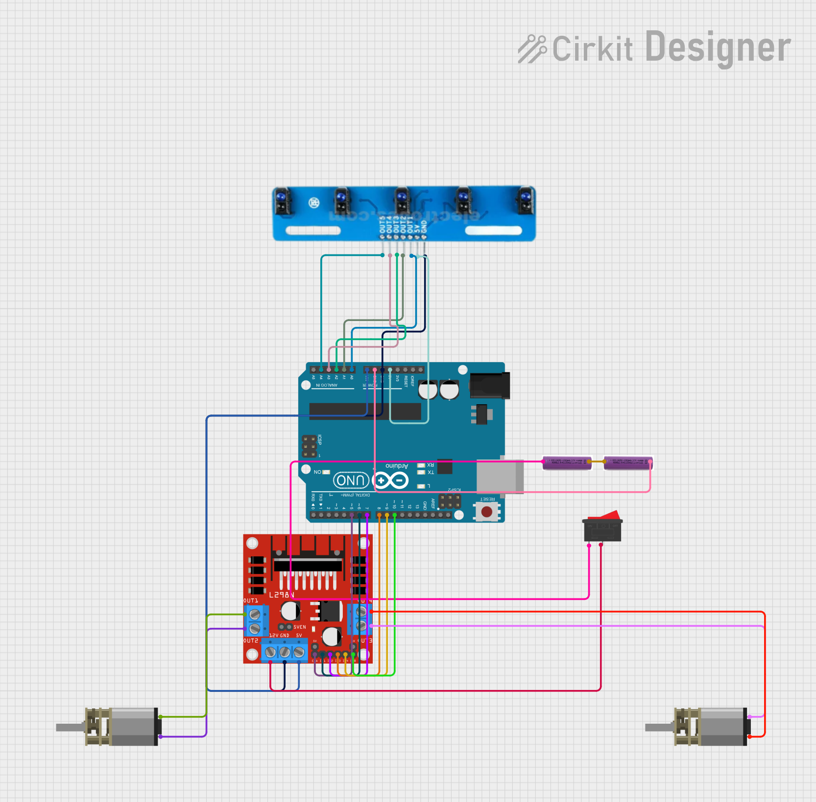
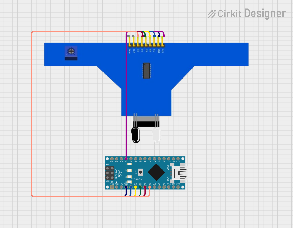
Connecting the 5 Channel IR Array to an Arduino UNO
To use the 5 Channel IR Array with an Arduino UNO, follow these steps:
Wiring:
- Connect the VCC pin of the IR array to the 5V pin on the Arduino.
- Connect the GND pin of the IR array to the GND pin on the Arduino.
- Connect the OUT1, OUT2, OUT3, OUT4, and OUT5 pins to any of the Arduino's digital input pins (e.g., D2 to D6).
Arduino Code: Use the following example code to read the outputs of the IR sensors and display the results in the Serial Monitor.
// Example code for interfacing a 5 Channel IR Array with Arduino UNO

// Define the digital pins connected to the IR array outputs
const int sensorPins[5] = {2, 3, 4, 5, 6};

void setup() {
  // Initialize serial communication for debugging
  Serial.begin(9600);

  // Set sensor pins as input
  for (int i = 0; i < 5; i++) {
    pinMode(sensorPins[i], INPUT);
  }
}

void loop() {
  // Read and print the state of each sensor
  Serial.print("Sensor States: ");
  for (int i = 0; i < 5; i++) {
    int sensorState = digitalRead(sensorPins[i]);
    Serial.print(sensorState);
    Serial.print(" "); // Add space between sensor states
  }
  Serial.println(); // Move to the next line
  delay(100); // Small delay for readability
}
Important Considerations:
- Surface Reflectivity: The detection range and accuracy depend on the reflectivity of the surface. Darker surfaces (e.g., black) reflect less IR light, while lighter surfaces (e.g., white) reflect more.
- Ambient Light: Avoid using the IR array in environments with strong ambient IR light (e.g., sunlight) as it may interfere with the sensor's performance.
- Power Supply: Ensure a stable power supply to avoid erratic sensor behavior.
4. Troubleshooting and FAQs
Common Issues and Solutions
| Issue | Possible Cause | Solution |
|---|---|---|
| No output from the sensors | Incorrect wiring or loose connections | Double-check all connections and ensure proper wiring. |
| Sensors give inconsistent readings | Ambient IR interference | Use the array in a controlled lighting environment or shield it from sunlight. |
| All sensors output HIGH or LOW | Faulty power supply or damaged sensors | Verify the power supply and replace the module if necessary. |
| Detection range is too short | Surface reflectivity is too low | Test with a more reflective surface or adjust the sensor's position. |
Frequently Asked Questions (FAQs)
Can I use the 5 Channel IR Array with a 3.3V microcontroller?
- Yes, the array is compatible with both 3.3V and 5V systems.
What is the maximum detection range of the IR sensors?
- The detection range is typically 2mm to 30mm, depending on the surface reflectivity.
Can I use fewer than 5 channels?
- Yes, you can use any number of channels by connecting only the required output pins to your microcontroller.
How do I calibrate the sensors for different surfaces?
- Calibration can be done by testing the array on the target surface and adjusting the sensor's position or sensitivity (if adjustable).
5. Conclusion
The 5 Channel Infrared (IR) Array is a powerful and versatile sensor module for multi-point IR detection. Its ease of use, compatibility with popular microcontrollers like the Arduino UNO, and wide range of applications make it an essential component for robotics and automation projects. By following the guidelines in this documentation, users can effectively integrate the IR array into their systems and troubleshoot common issues with ease.
For further assistance, refer to the manufacturer's datasheet or community forums for additional support.
Explore Projects Built with 5 channel IR array
Explore Projects Built with 5 channel IR array