How to Use Adafruit TXB0104 4-channel Bi-Directional Level Shifter: Examples, Pinouts, and Specs
Introduction
The Adafruit TXB0104 is a versatile 4-channel bi-directional level shifter designed to interface between devices operating at different voltage levels. This component is essential for mixed-voltage level circuits, allowing for safe and reliable communication between devices such as microcontrollers, sensors, and other integrated circuits that operate at varying logic levels.
Explore Projects Built with Adafruit TXB0104 4-channel Bi-Directional Level Shifter

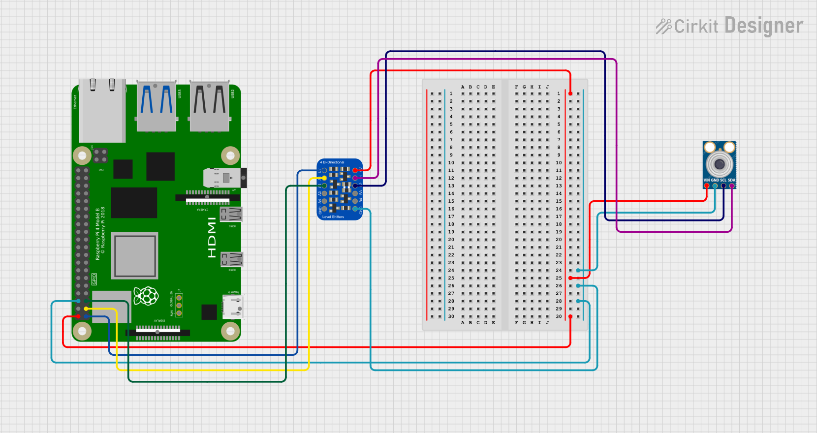
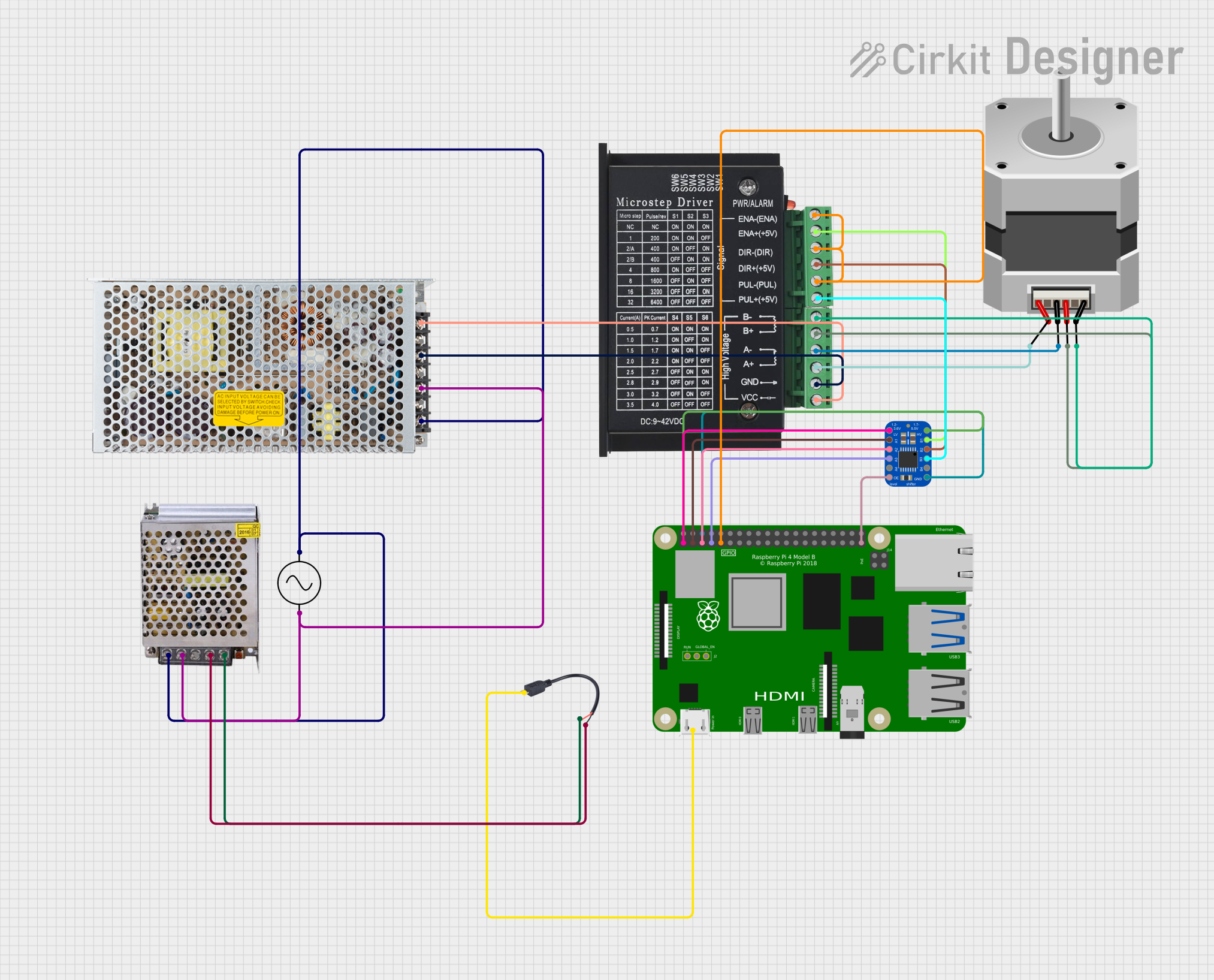

Explore Projects Built with Adafruit TXB0104 4-channel Bi-Directional Level Shifter
Common Applications and Use Cases
- Interfacing 3.3V sensors with 5V microcontrollers
- Connecting 1.8V or 2.5V devices to a 3.3V system
- Bridging communication between an Arduino UNO (operating at 5V) and newer devices that require 3.3V logic levels
- Prototyping with mixed-voltage level components on a breadboard
Technical Specifications
Key Technical Details
- Voltage Levels: Bidirectional translation between 1.2V to 3.6V on the low side and 1.65V to 5.5V on the high side
- Channels: 4 bidirectional channels
- Current Rating: 4 mA per channel
- Switching Speed: Up to 100 Mbps (for 3.3V to 5V translation)
- ESD Protection: 15 kV Human Body Model (HBM)
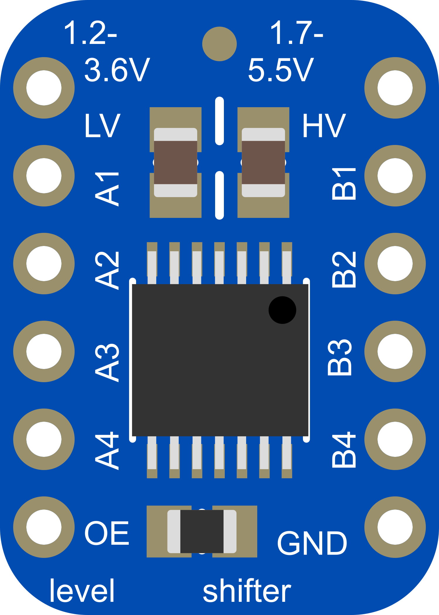
Pin Configuration and Descriptions
| Pin Number | Name | Description |
|---|---|---|
| 1 | OE | Output Enable (active-high) |
| 2-5 | B1-B4 | High-voltage side pins |
| 6 | GND | Ground reference for the low-voltage side |
| 7-10 | A1-A4 | Low-voltage side pins |
| 11 | GND | Ground reference for the high-voltage side |
| 12 | VCCA | Low-voltage supply (1.2V to 3.6V) |
| 13 | VCCB | High-voltage supply (1.65V to 5.5V) |
| 14 | NC | No Connection (do not connect) |
Usage Instructions
How to Use the Component in a Circuit
- Power Supply: Connect VCCA to the lower voltage supply and VCCB to the higher voltage supply. Ensure that both grounds (pin 6 and 11) are connected to the common ground of your system.
- Signal Connections: Connect the low-voltage signals to A1-A4 and the corresponding high-voltage signals to B1-B4.
- Output Enable: Connect the OE pin to a high logic level (usually to VCCB) to enable the device. If you need to disable the level shifter temporarily, you can pull this pin low.
Important Considerations and Best Practices
- Power Sequencing: VCCA must be supplied before (or at the same time as) VCCB to ensure proper operation.
- Signal Integrity: Keep the traces as short as possible to minimize signal degradation, especially at high speeds.
- Decoupling Capacitors: Place a 0.1 µF capacitor close to the VCCA and VCCB pins to filter out noise.
- Avoid Floating Inputs: Ensure that all input pins are driven to a valid logic level; do not leave them floating.
Example Connection with Arduino UNO
// Example code for interfacing a 3.3V sensor with a 5V Arduino UNO using the TXB0104 level shifter

// Define the sensor's data pin connected to the level shifter's low-voltage side (A1)
const int sensorPin = 2; // Arduino pin connected to TXB0104 A1

void setup() {
  // Initialize the sensor's data pin as an input
  pinMode(sensorPin, INPUT);
}

void loop() {
  // Read the sensor's data
  int sensorValue = digitalRead(sensorPin);

  // Process the sensor data (for demonstration purposes, we'll just print it)
  Serial.begin(9600);
  Serial.println(sensorValue);

  // Add a delay between reads for stability
  delay(500);
}
Troubleshooting and FAQs
Common Issues
- No Signal Conversion: Ensure that the OE pin is set high and that the power supply voltages are correct and stable.
- Intermittent Functionality: Check for loose connections and verify that the decoupling capacitors are in place.
- Signal Distortion: Reduce the length of the connections and ensure that the data rate does not exceed the component's specifications.
Solutions and Tips for Troubleshooting
- Power Supply Issues: Use a multimeter to verify that VCCA and VCCB are at the correct levels.
- OE Pin State: Confirm that the OE pin is connected properly and is receiving a high logic level.
- Input Levels: Make sure that the input signals are within the specified range for the respective voltage side.
FAQs
Q: Can the TXB0104 be used for I2C or SPI communication? A: The TXB0104 is not recommended for I2C due to the lack of open-drain structure. For SPI, it can be used if the clock speeds are within the component's operating range.
Q: What happens if VCCA is higher than VCCB? A: The TXB0104 is designed to have VCCA at a lower voltage than VCCB. Applying a higher voltage to VCCA can damage the device.
Q: Is it necessary to connect all channels even if they are not in use? A: No, it is not necessary to connect all channels. Unused channels can be left unconnected. However, ensure that unused input pins are not left floating.
Q: Can the TXB0104 be used in a permanent installation? A: Yes, the TXB0104 can be used in permanent installations, provided that the design follows the recommended best practices for signal integrity and power supply stability.