
How to Use AD9850: Examples, Pinouts, and Specs
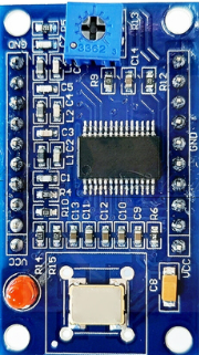
 Design with AD9850 in Cirkit Designer
Introduction
The AD9850 is a high-performance Direct Digital Synthesizer (DDS) manufactured by Analog Devices, with the part ID AD9850BRSZ. It is designed to generate precise sine and square waveforms with high frequency resolution and low phase noise. The AD9850 is widely used in signal generation applications, including RF systems, audio signal processing, and function generators. Its compact design and versatile functionality make it a popular choice for both hobbyists and professionals.
Explore Projects Built with AD9850
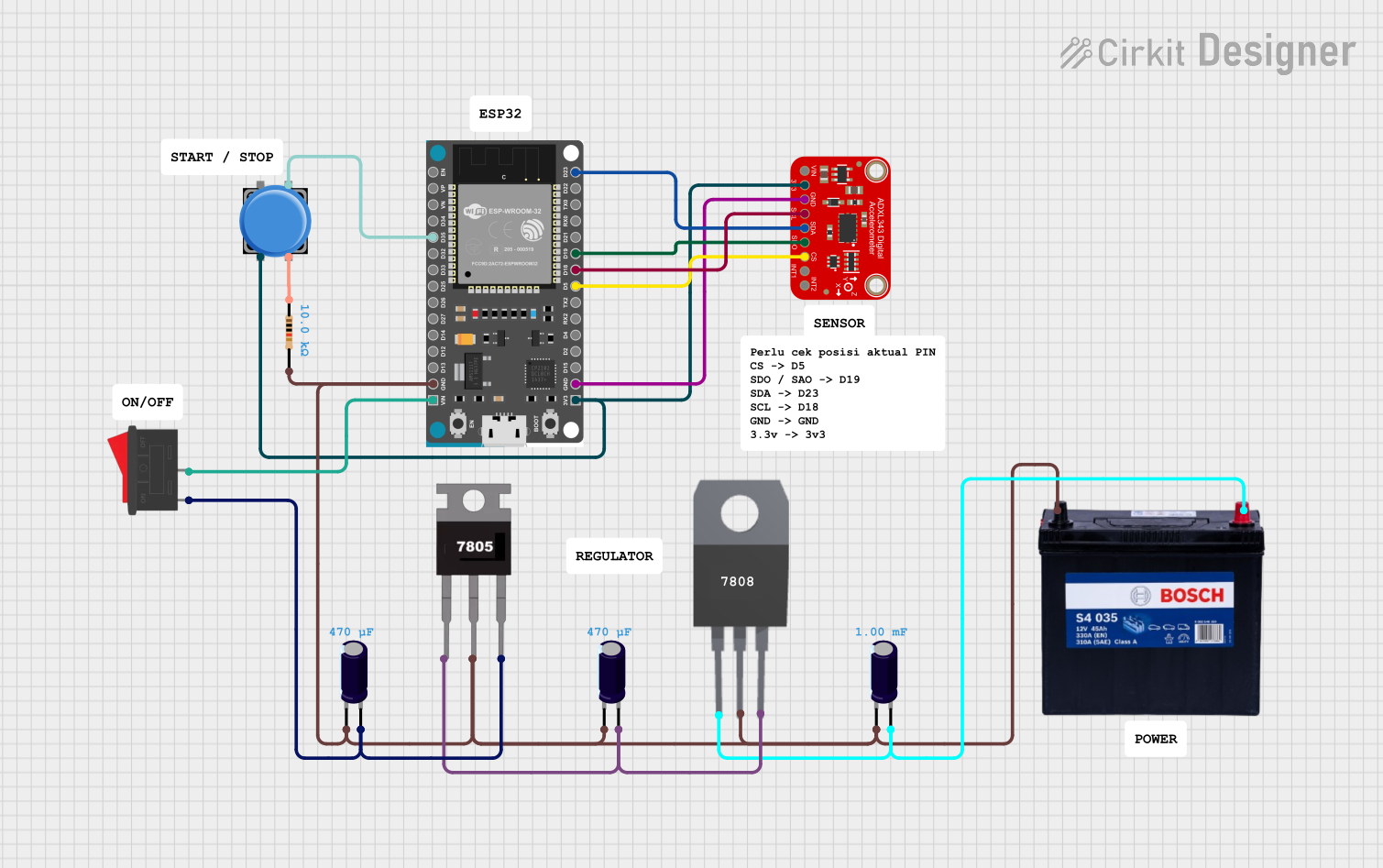 Open Project in Cirkit Designer
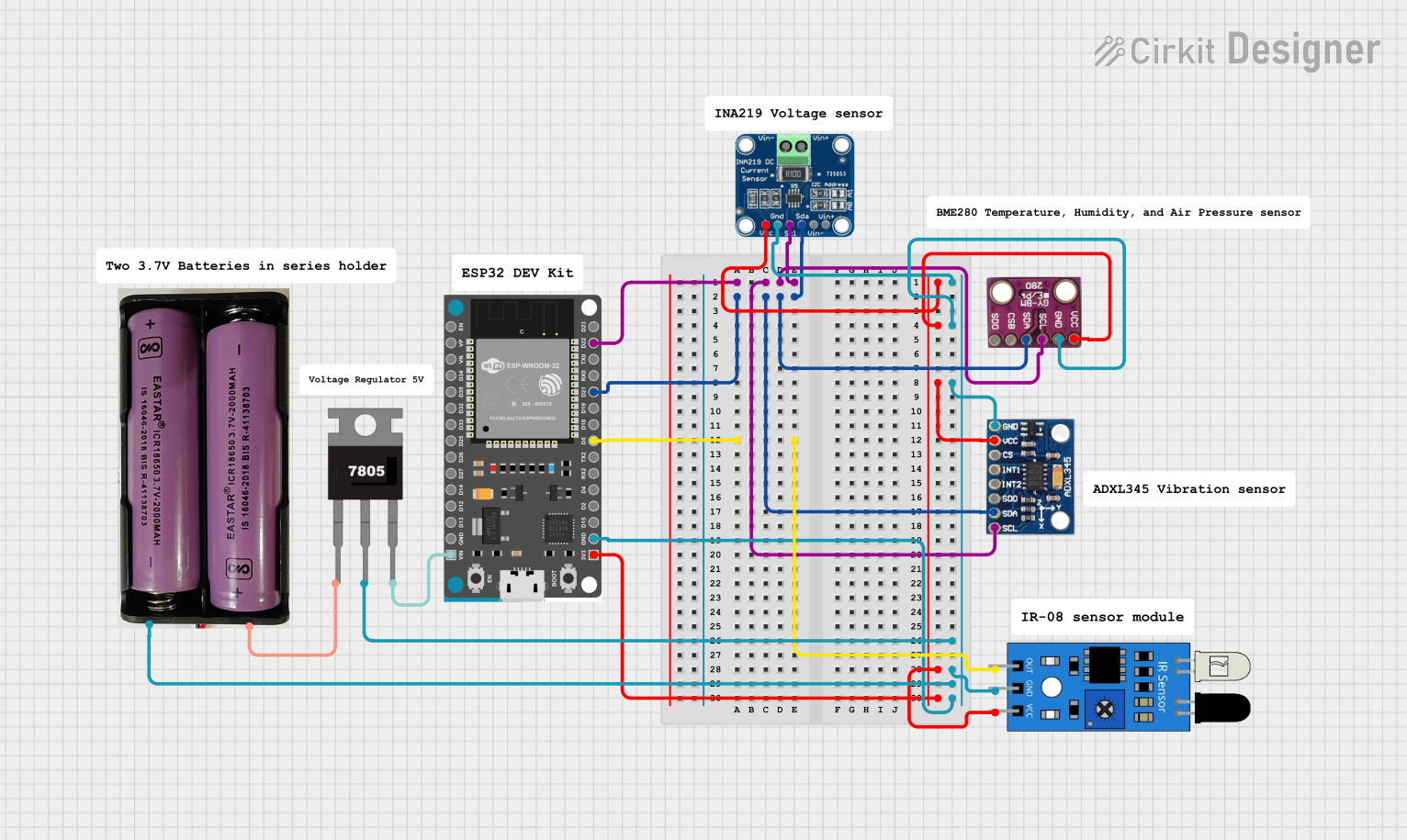 Open Project in Cirkit Designer
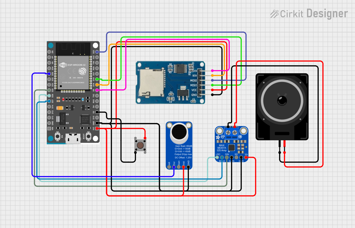 Open Project in Cirkit Designer
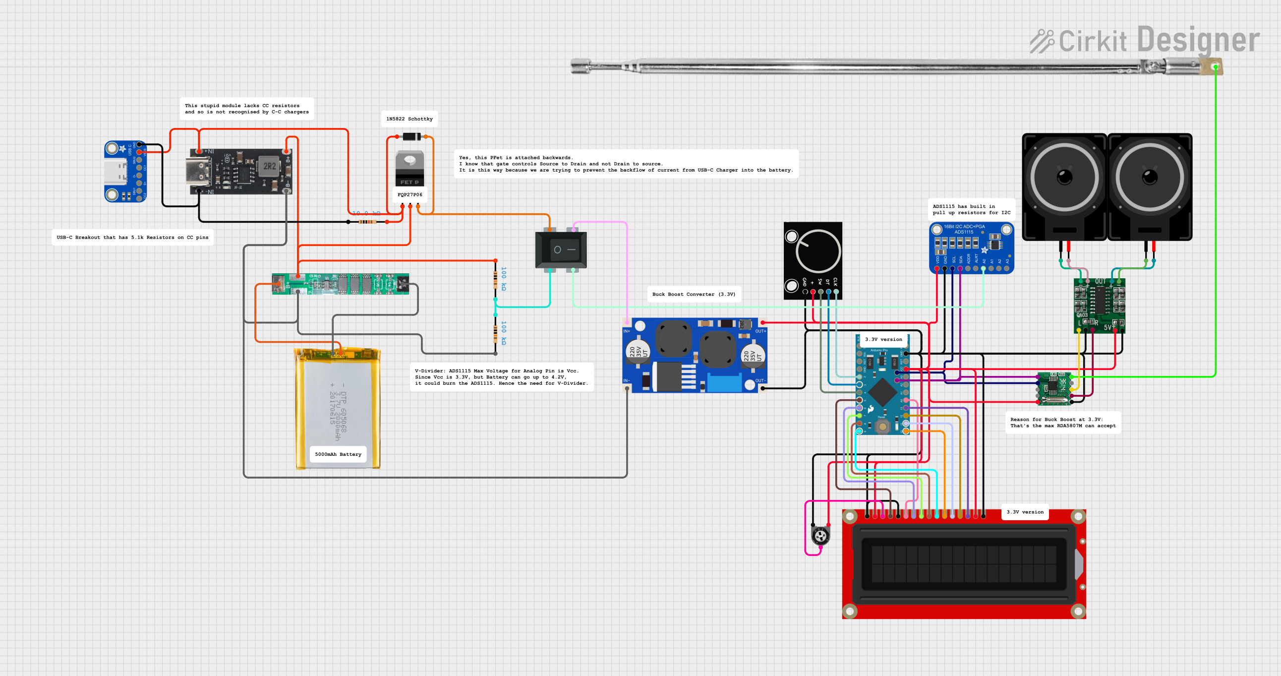 Open Project in Cirkit Designer
Explore Projects Built with AD9850
Open Project in Cirkit DesignerOpen Project in Cirkit DesignerOpen Project in Cirkit DesignerOpen Project in Cirkit DesignerCommon Applications
- RF signal generation for communication systems
- Audio signal processing and testing
- Function generators and waveform synthesis
- Frequency modulation and phase modulation systems
- Clock generation for digital systems
Technical Specifications
The following table outlines the key technical details of the AD9850:
| Parameter | Value |
|---|---|
| Supply Voltage (Vcc) | 2.7V to 5.5V |
| Power Consumption | 380 mW (typical at 5V) |
| Frequency Range | Up to 125 MHz |
| Frequency Resolution | 32-bit tuning word (0.0291 Hz at 125 MHz clock) |
| Phase Noise | -140 dBc/Hz at 1 kHz offset |
| Output Waveforms | Sine wave, Square wave |
| DAC Resolution | 10-bit |
| Operating Temperature Range | -40°C to +85°C |
| Package Type | 28-lead SSOP |
Pin Configuration and Descriptions
The AD9850 has 28 pins, with the following configuration:
| Pin Number | Pin Name | Description |
|---|---|---|
| 1 | VCC | Positive power supply (2.7V to 5.5V) |
| 2 | GND | Ground |
| 3 | W_CLK | Word clock input for serial data |
| 4 | FQ_UD | Frequency update input |
| 5 | DATA | Serial data input |
| 6 | RESET | Reset input (active high) |
| 7-14 | NC | No connection |
| 15 | REF_CLK | Reference clock input (up to 125 MHz) |
| 16 | DAC_OUT | Analog sine wave output |
| 17 | COMP1 | DAC comparator input 1 |
| 18 | COMP2 | DAC comparator input 2 |
| 19 | IOUT | Current output for sine wave |
| 20 | GND | Ground |
| 21-28 | NC | No connection |
Usage Instructions
How to Use the AD9850 in a Circuit
- Power Supply: Connect the VCC pin to a stable power source (2.7V to 5.5V) and the GND pin to ground.
- Reference Clock: Provide a stable reference clock signal to the REF_CLK pin. A crystal oscillator or external clock source can be used.
- Serial Communication: Use the W_CLK, FQ_UD, DATA, and RESET pins to configure the frequency and phase of the output waveform. These pins are controlled via a microcontroller or FPGA.
- Output Waveform: The sine wave output is available at the DAC_OUT pin, while the square wave output can be derived from the IOUT pin.
Important Considerations
- Use decoupling capacitors (e.g., 0.1 µF) near the VCC pin to reduce noise.
- Ensure the reference clock signal is clean and stable for accurate frequency generation.
- Avoid exceeding the maximum input voltage or current ratings to prevent damage.
- Use proper termination for the output signals to maintain signal integrity.
Example: Connecting AD9850 to Arduino UNO
The AD9850 can be easily interfaced with an Arduino UNO for frequency generation. Below is an example code to generate a 1 MHz sine wave:
// Include necessary libraries
#include <SPI.h>

// Define AD9850 control pins
#define W_CLK 8    // Word clock pin
#define FQ_UD 9    // Frequency update pin
#define DATA 10    // Serial data pin
#define RESET 11   // Reset pin

void setup() {
  // Set control pins as outputs
  pinMode(W_CLK, OUTPUT);
  pinMode(FQ_UD, OUTPUT);
  pinMode(DATA, OUTPUT);
  pinMode(RESET, OUTPUT);

  // Initialize pins
  digitalWrite(W_CLK, LOW);
  digitalWrite(FQ_UD, LOW);
  digitalWrite(DATA, LOW);
  digitalWrite(RESET, LOW);

  // Reset the AD9850
  digitalWrite(RESET, HIGH);
  delay(1);
  digitalWrite(RESET, LOW);

  // Set frequency to 1 MHz
  setFrequency(1000000); // Frequency in Hz
}

void loop() {
  // The AD9850 will continuously output the set frequency
}

// Function to set frequency
void setFrequency(unsigned long frequency) {
  unsigned long tuningWord = (frequency * pow(2, 32)) / 125000000;
  // Calculate tuning word based on reference clock (125 MHz)

  for (int i = 0; i < 4; i++) {
    shiftOut(DATA, W_CLK, LSBFIRST, tuningWord & 0xFF);
    // Send 8 bits of the tuning word (LSB first)
    tuningWord >>= 8; // Shift to the next byte
  }

  shiftOut(DATA, W_CLK, LSBFIRST, 0x00); // Phase word (default 0)
  digitalWrite(FQ_UD, HIGH); // Update frequency
  digitalWrite(FQ_UD, LOW);
}
Notes:
- Replace the reference clock frequency in the
setFrequencyfunction if using a clock other than 125 MHz. - Ensure proper connections between the Arduino and AD9850 pins.
Troubleshooting and FAQs
Common Issues
No Output Signal:
- Verify the power supply and ground connections.
- Ensure the reference clock signal is present and within the specified range.
- Check the serial communication pins for proper connections.
Incorrect Frequency Output:
- Confirm the reference clock frequency matches the value used in calculations.
- Verify the tuning word calculation in the code.
High Noise in Output Signal:
- Use proper decoupling capacitors near the power supply pins.
- Ensure the output signal is terminated correctly.
FAQs
Q: Can the AD9850 generate square waves directly?
A: Yes, the AD9850 can generate square waves using the IOUT pin. However, additional circuitry may be required to condition the signal.
Q: What is the maximum frequency the AD9850 can generate?
A: The AD9850 can generate frequencies up to 62.5 MHz for sine waves, which is half of the reference clock frequency (Nyquist limit).
Q: Can I use a lower reference clock frequency?
A: Yes, the AD9850 supports reference clock frequencies below 125 MHz, but this will reduce the maximum output frequency and resolution.
Q: How do I improve phase noise performance?
A: Use a high-quality, low-jitter reference clock source and ensure proper grounding and decoupling in the circuit design.