Cirkit Designer Logo
Cirkit Designer
Your all-in-one circuit design IDE
Home / 
Component Documentation

How to Use Adafruit Pixie: Examples, Pinouts, and Specs

Image of Adafruit Pixie
Cirkit Designer LogoDesign with Adafruit Pixie in Cirkit Designer

Introduction

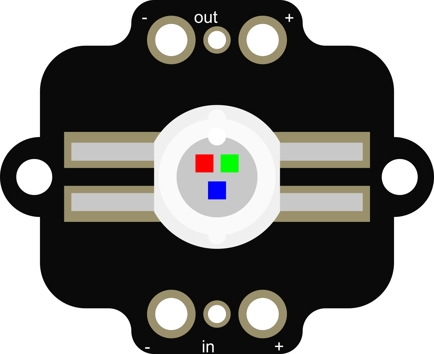
The Adafruit Pixie is a compact, chainable, and programmable RGB LED board that is perfect for adding vibrant and colorful lighting effects to your projects. Each Pixie module features 5 individually addressable LEDs, allowing for a wide range of color mixing and animation possibilities. Common applications include wearable electronics, custom lighting setups, and interactive art installations.

Explore Projects Built with Adafruit Pixie

Use Cirkit Designer to design, explore, and prototype these projects online. Some projects support real-time simulation. Click "Open Project" to start designing instantly!
Battery-Powered Smart Sensor Hub with Adafruit QT Py RP2040
Image of wearable final: A project utilizing Adafruit Pixie in a practical application
This circuit features an Adafruit QT Py RP2040 microcontroller interfaced with an APDS9960 proximity sensor, an MPU6050 accelerometer and gyroscope, and an OLED display via I2C communication. It also includes a buzzer controlled by the microcontroller and is powered by a 3.7V LiPo battery with a toggle switch for power control.
Cirkit Designer LogoOpen Project in Cirkit Designer
Battery-Powered Smart Light with Proximity Sensor and OLED Display using Adafruit QT Py RP2040
Image of lab: A project utilizing Adafruit Pixie in a practical application
This circuit is a portable, battery-powered system featuring an Adafruit QT Py RP2040 microcontroller that interfaces with an OLED display, a proximity sensor, an accelerometer, and an RGB LED strip. The system is powered by a lithium-ion battery with a step-up boost converter to provide 5V for the LED strip, and it includes a toggle switch for power control. The microcontroller communicates with the sensors and display via I2C.
Cirkit Designer LogoOpen Project in Cirkit Designer
Battery-Powered Sensor Hub with Adafruit QT Py RP2040 and OLED Display
Image of 512: A project utilizing Adafruit Pixie in a practical application
This circuit features an Adafruit QT Py RP2040 microcontroller interfacing with an MPU-6050 accelerometer, an Adafruit APDS-9960 sensor, and a 0.96" OLED display via I2C communication. It is powered by a 3.7V LiPo battery and includes a green LED with a current-limiting resistor connected to an analog pin of the microcontroller.
Cirkit Designer LogoOpen Project in Cirkit Designer
ATmega328P-Based Sensor Hub with OLED Display and LIDAR
Image of TILTPCB: A project utilizing Adafruit Pixie in a practical application
This circuit features an Mtiny Uno ATmega328P microcontroller as its central processing unit, interfacing with a variety of sensors and peripherals. It includes a 0.96" OLED display and an MPU6050 accelerometer/gyroscope for user interface and motion sensing, respectively. The circuit also integrates a TF LUNA LIDAR for distance measurement, a DHT11 sensor for temperature and humidity readings, and uses a 9V battery with a 7805 voltage regulator for power management. Communication with a computer for programming and data exchange is facilitated by an Adafruit FTDI Friend module.
Cirkit Designer LogoOpen Project in Cirkit Designer

Explore Projects Built with Adafruit Pixie

Use Cirkit Designer to design, explore, and prototype these projects online. Some projects support real-time simulation. Click "Open Project" to start designing instantly!
Image of wearable final: A project utilizing Adafruit Pixie in a practical application
Battery-Powered Smart Sensor Hub with Adafruit QT Py RP2040
This circuit features an Adafruit QT Py RP2040 microcontroller interfaced with an APDS9960 proximity sensor, an MPU6050 accelerometer and gyroscope, and an OLED display via I2C communication. It also includes a buzzer controlled by the microcontroller and is powered by a 3.7V LiPo battery with a toggle switch for power control.
Cirkit Designer LogoOpen Project in Cirkit Designer
Image of lab: A project utilizing Adafruit Pixie in a practical application
Battery-Powered Smart Light with Proximity Sensor and OLED Display using Adafruit QT Py RP2040
This circuit is a portable, battery-powered system featuring an Adafruit QT Py RP2040 microcontroller that interfaces with an OLED display, a proximity sensor, an accelerometer, and an RGB LED strip. The system is powered by a lithium-ion battery with a step-up boost converter to provide 5V for the LED strip, and it includes a toggle switch for power control. The microcontroller communicates with the sensors and display via I2C.
Cirkit Designer LogoOpen Project in Cirkit Designer
Image of 512: A project utilizing Adafruit Pixie in a practical application
Battery-Powered Sensor Hub with Adafruit QT Py RP2040 and OLED Display
This circuit features an Adafruit QT Py RP2040 microcontroller interfacing with an MPU-6050 accelerometer, an Adafruit APDS-9960 sensor, and a 0.96" OLED display via I2C communication. It is powered by a 3.7V LiPo battery and includes a green LED with a current-limiting resistor connected to an analog pin of the microcontroller.
Cirkit Designer LogoOpen Project in Cirkit Designer
Image of TILTPCB: A project utilizing Adafruit Pixie in a practical application
ATmega328P-Based Sensor Hub with OLED Display and LIDAR
This circuit features an Mtiny Uno ATmega328P microcontroller as its central processing unit, interfacing with a variety of sensors and peripherals. It includes a 0.96" OLED display and an MPU6050 accelerometer/gyroscope for user interface and motion sensing, respectively. The circuit also integrates a TF LUNA LIDAR for distance measurement, a DHT11 sensor for temperature and humidity readings, and uses a 9V battery with a 7805 voltage regulator for power management. Communication with a computer for programming and data exchange is facilitated by an Adafruit FTDI Friend module.
Cirkit Designer LogoOpen Project in Cirkit Designer

Technical Specifications

Key Technical Details

  • Supply Voltage: 4-7V DC
  • Control Signal: Digital UART at 115200 baud (8N1)
  • Current Draw: Up to ~18mA per LED at full brightness
  • Brightness: Adjustable via software
  • LED Type: High-brightness, surface-mount RGB LEDs
  • Dimensions: 19mm x 10mm x 2mm

Pin Configuration and Descriptions

Pin Number Name Description
1 VCC Power supply (4-7V DC)
2 TX UART transmit to Pixie
3 RX UART receive from previous Pixie (for chaining)
4 GND Ground connection

Usage Instructions

Integrating Pixie into a Circuit

  1. Power Supply: Connect the VCC pin to a 4-7V power supply and the GND pin to the common ground.
  2. Signal Connection: Connect the TX pin to the UART transmit pin of your microcontroller.
  3. Chaining Pixies: To chain multiple Pixies, connect the RX pin of one Pixie to the TX pin of the next.
  4. Programming: Use a microcontroller to send serial data to the Pixie at 115200 baud to control the color of the LEDs.

Important Considerations and Best Practices

  • Ensure that your power supply can handle the current requirements when all LEDs are at full brightness.
  • Use a common ground for all components in your circuit.
  • When chaining Pixies, keep the connections as short as possible to ensure reliable communication.
  • Always include a current-limiting resistor if you are powering the Pixie from a source higher than 7V.

Example Code for Arduino UNO

#include <SoftwareSerial.h>

SoftwareSerial pixieSerial(-1, 6); // RX, TX

void setup() {
  pixieSerial.begin(115200); // Start serial communication at 115200 baud
}

void loop() {
  // Send a color to the Pixie
  // Colors are sent as 3 bytes, one for each color (R, G, B)
  pixieSerial.write(255); // Red
  pixieSerial.write(0);   // Green
  pixieSerial.write(0);   // Blue
  
  delay(500); // Wait for half a second
  
  // Send another color
  pixieSerial.write(0);   // Red
  pixieSerial.write(255); // Green
  pixieSerial.write(0);   // Blue
  
  delay(500); // Wait for half a second
}

Note: The -1 in SoftwareSerial indicates that we're not using the RX pin in this example. The TX pin is connected to pin 6 on the Arduino.

Troubleshooting and FAQs

Common Issues

  • Pixie not lighting up: Check the power supply and connections. Ensure the Pixie is receiving the correct voltage.
  • Incorrect colors displayed: Verify that the data is being sent in the correct order (R, G, B) and at the correct baud rate.
  • Communication issues when chaining: Reduce the length of the connections between Pixies or check for any loose connections.

Solutions and Tips

  • Use a multimeter to check for proper voltage levels at the Pixie's VCC and GND pins.
  • Ensure that the microcontroller's UART settings match the Pixie's requirements (115200 baud, 8N1).
  • For long chains of Pixies, consider using a buffer or a level shifter to maintain signal integrity.

FAQs

Q: How many Pixies can I chain together? A: The number of Pixies you can chain is limited by the power supply and the ability of the microcontroller to drive the signal down the chain. Keep the total current draw in mind.

Q: Can I use the Pixie with a 3.3V microcontroller? A: Yes, but ensure that the Pixie is powered with a voltage within its specified range (4-7V). The data signal from a 3.3V microcontroller should be sufficient for communication.

Q: How do I program complex animations? A: Complex animations require careful timing and sequencing of color changes. You can use arrays to store color patterns and loops to iterate through them.

For further assistance, visit the Adafruit support forums or the Pixie product page for additional resources and community projects.