How to Use lcd: Examples, Pinouts, and Specs
Introduction
A Liquid Crystal Display (LCD) is a flat-panel display technology that uses liquid crystals to modulate light. It is widely used in various applications due to its lightweight, energy-efficient, and versatile nature. LCDs are commonly found in devices such as televisions, computer monitors, mobile phones, and embedded systems. In electronics, smaller LCD modules are often used to display alphanumeric characters, symbols, or graphical data in projects and devices.
Explore Projects Built with lcd


Explore Projects Built with lcd
Common Applications and Use Cases
- Digital clocks and watches
- Embedded systems and microcontroller projects
- Consumer electronics (e.g., calculators, remote controls)
- Industrial control panels
- Portable medical devices
- Educational and prototyping purposes
Technical Specifications
Below are the general technical specifications for a standard 16x2 alphanumeric LCD module (e.g., HD44780-compatible):
Key Technical Details
- Display Type: 16x2 (16 characters per row, 2 rows)
- Operating Voltage: 4.7V to 5.3V DC
- Current Consumption: ~1mA (without backlight), ~15mA (with backlight)
- Backlight: LED (commonly white, green, or blue)
- Interface: Parallel (4-bit or 8-bit mode)
- Character Size: ~5.0mm x 8.0mm
- Operating Temperature: -20°C to 70°C
- Storage Temperature: -30°C to 80°C
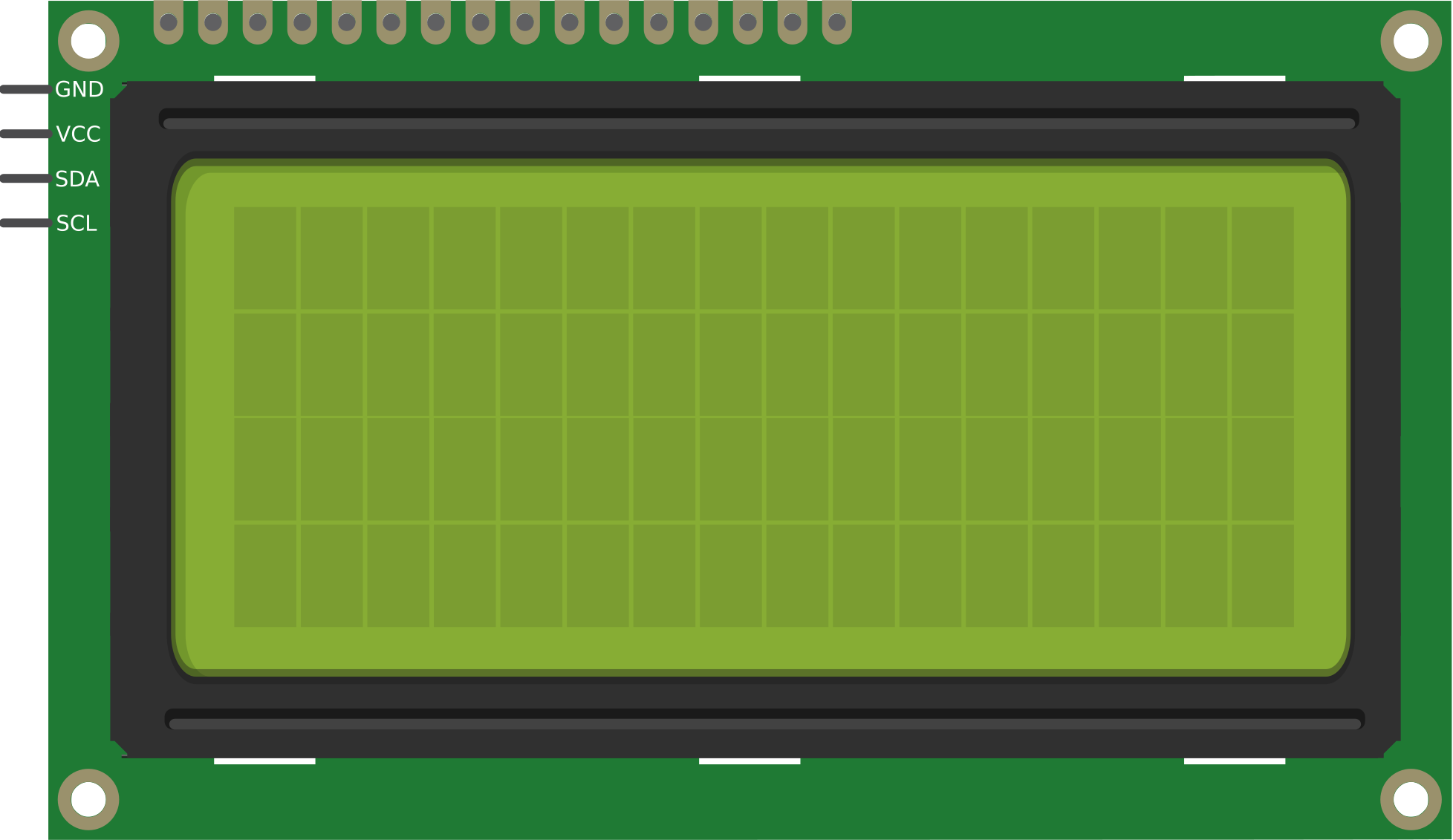
Pin Configuration and Descriptions
The standard 16x2 LCD module typically has 16 pins. Below is the pinout and description:
| Pin Number | Name | Description |
|---|---|---|
| 1 | VSS | Ground (0V) connection. |
| 2 | VDD | Power supply (4.7V to 5.3V). |
| 3 | VO | Contrast adjustment (connect to a potentiometer for contrast control). |
| 4 | RS | Register Select (0: Command mode, 1: Data mode). |
| 5 | RW | Read/Write (0: Write to LCD, 1: Read from LCD). |
| 6 | E | Enable pin (triggers data read/write). |
| 7 | D0 | Data pin 0 (used in 8-bit mode only). |
| 8 | D1 | Data pin 1 (used in 8-bit mode only). |
| 9 | D2 | Data pin 2 (used in 8-bit mode only). |
| 10 | D3 | Data pin 3 (used in 8-bit mode only). |
| 11 | D4 | Data pin 4 (used in both 4-bit and 8-bit modes). |
| 12 | D5 | Data pin 5 (used in both 4-bit and 8-bit modes). |
| 13 | D6 | Data pin 6 (used in both 4-bit and 8-bit modes). |
| 14 | D7 | Data pin 7 (used in both 4-bit and 8-bit modes). |
| 15 | A/LED+ | Anode of the backlight LED (connect to 5V through a resistor). |
| 16 | K/LED- | Cathode of the backlight LED (connect to ground). |
Usage Instructions
How to Use the Component in a Circuit
- Power Supply: Connect the VSS pin to ground and the VDD pin to a 5V power source.
- Contrast Adjustment: Connect the VO pin to the wiper of a 10kΩ potentiometer. Connect one end of the potentiometer to ground and the other to 5V. Adjust the potentiometer to set the display contrast.
- Control Pins: Connect the RS, RW, and E pins to digital output pins of a microcontroller (e.g., Arduino).
- Data Pins: For 4-bit mode, connect D4 to D7 to the microcontroller. For 8-bit mode, connect all data pins (D0 to D7).
- Backlight: Connect the A/LED+ pin to 5V through a current-limiting resistor (e.g., 220Ω). Connect the K/LED- pin to ground.
Important Considerations and Best Practices
- Use a current-limiting resistor for the backlight to prevent damage.
- Ensure proper grounding to avoid noise or flickering issues.
- Use decoupling capacitors (e.g., 0.1µF) near the power pins for stable operation.
- Avoid leaving the RW pin floating; connect it to ground if only writing to the LCD.
- For 4-bit mode, send data in two 4-bit nibbles (high nibble first).
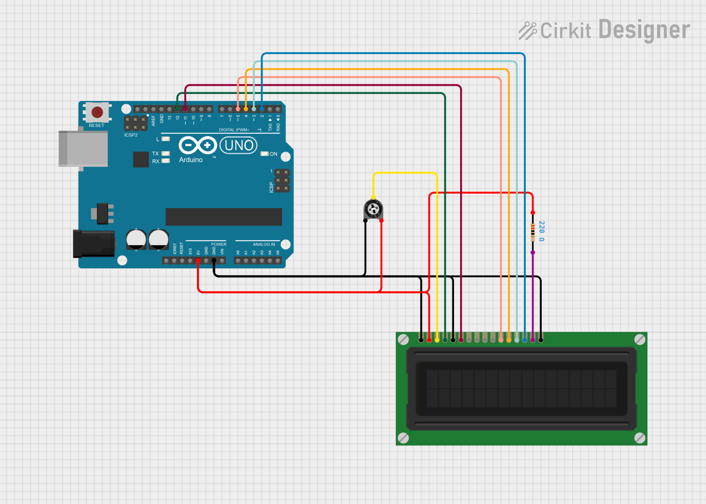
Example: Connecting to an Arduino UNO
Below is an example of how to connect and program a 16x2 LCD with an Arduino UNO in 4-bit mode:
Circuit Connections
- RS: Arduino pin 7
- E: Arduino pin 8
- D4: Arduino pin 9
- D5: Arduino pin 10
- D6: Arduino pin 11
- D7: Arduino pin 12
- VO: Middle pin of a 10kΩ potentiometer (ends connected to 5V and GND)
- A/LED+: 5V through a 220Ω resistor
- K/LED-: GND
Arduino Code
#include <LiquidCrystal.h>

// Initialize the library with the pins connected to the LCD
// (RS, E, D4, D5, D6, D7)
LiquidCrystal lcd(7, 8, 9, 10, 11, 12);

void setup() {
  // Set up the LCD's number of columns and rows
  lcd.begin(16, 2);

  // Print a message to the LCD
  lcd.print("Hello, World!");
}

void loop() {
  // Move the cursor to the second row, first column
  lcd.setCursor(0, 1);

  // Print a dynamic message
  lcd.print("Count: ");
  lcd.print(millis() / 1000); // Display elapsed time in seconds
}
Troubleshooting and FAQs
Common Issues and Solutions
No Display or Blank Screen:
- Check the power connections (VSS to GND, VDD to 5V).
- Adjust the contrast using the potentiometer connected to VO.
- Ensure the backlight is properly connected.
Flickering or Unstable Display:
- Verify proper grounding and decoupling capacitors near the power pins.
- Check for loose or poor connections in the circuit.
Incorrect or Garbled Characters:
- Ensure the data pins are correctly connected to the microcontroller.
- Verify the code matches the wiring configuration (e.g., pin assignments).
Backlight Not Working:
- Check the current-limiting resistor and connections to A/LED+ and K/LED-.
- Ensure the backlight is not drawing excessive current.
FAQs
Q: Can I use the LCD with a 3.3V microcontroller?
A: Yes, but you may need a level shifter for the control and data pins. Additionally, check if the backlight operates at 3.3V or requires a separate 5V supply.
Q: How do I display custom characters?
A: Use the createChar() function in the LiquidCrystal library to define and display custom characters.
Q: Can I use the LCD in 8-bit mode?
A: Yes, connect all data pins (D0 to D7) to the microcontroller and modify the code accordingly. However, 4-bit mode is more common as it uses fewer pins.
Q: What is the maximum cable length for connecting the LCD?
A: Keep the cable length as short as possible (preferably under 30cm) to avoid signal degradation and noise issues. Use shielded cables if longer distances are required.