
How to Use LED Controller: Examples, Pinouts, and Specs
 Design with LED Controller in Cirkit Designer
Introduction
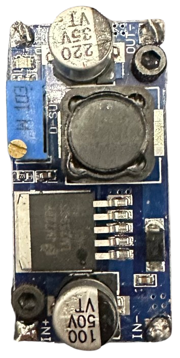
An LED Controller is a device designed to manage the operation of LED lights, enabling users to control brightness, color, and lighting effects. These controllers are essential for creating dynamic lighting environments in applications such as home automation, decorative lighting, stage lighting, and signage. They often support various input methods, including manual controls, remote controls, or digital interfaces like DMX or PWM signals.
Common applications include:
- Smart home lighting systems
- RGB or RGBW LED strip control
- Architectural and decorative lighting
- Stage and event lighting
- Automotive LED lighting
Explore Projects Built with LED Controller
 Open Project in Cirkit Designer
 Open Project in Cirkit Designer
 Open Project in Cirkit Designer
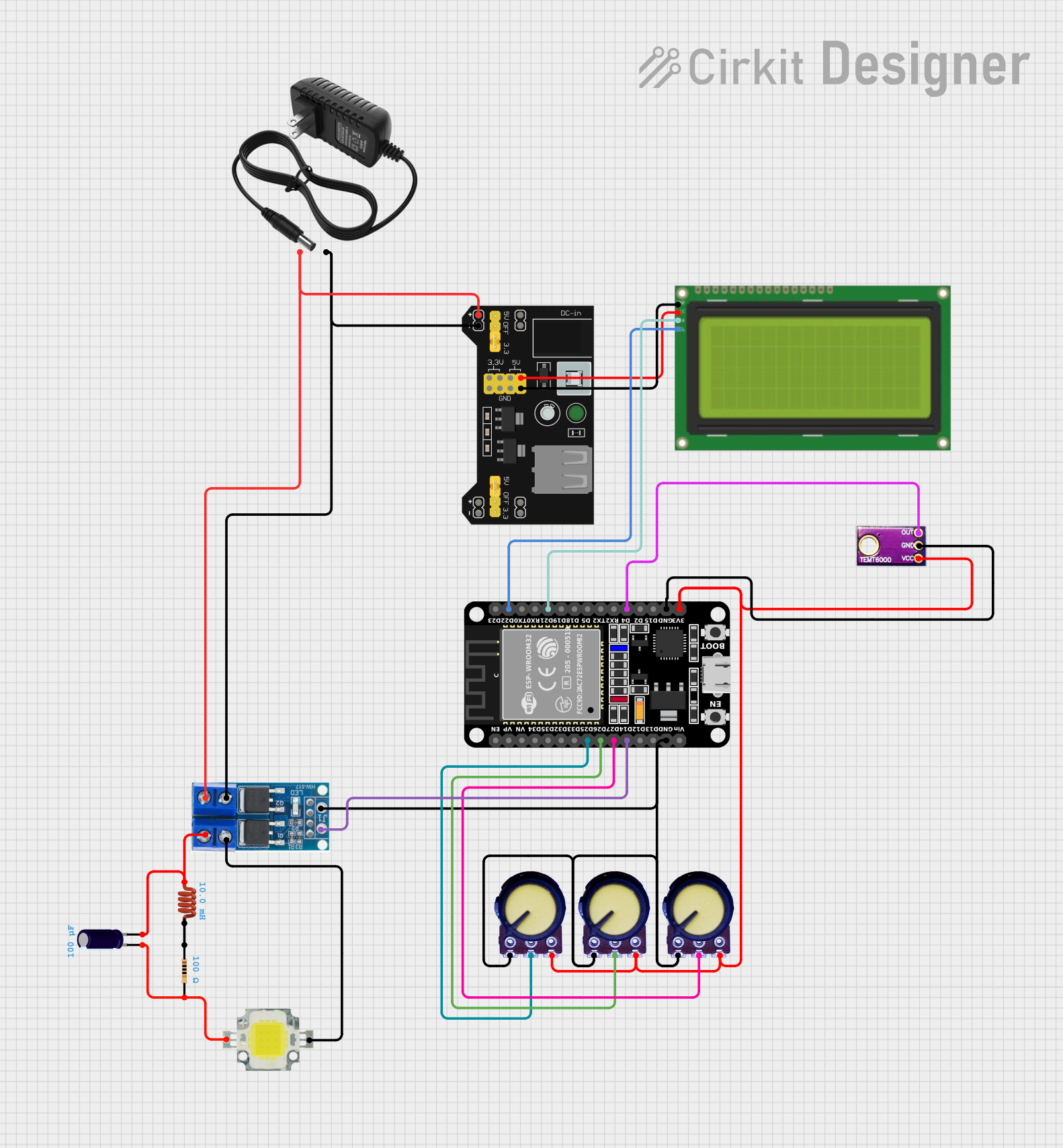
 Open Project in Cirkit Designer
Explore Projects Built with LED Controller

 Open Project in Cirkit Designer
 Open Project in Cirkit Designer
 Open Project in Cirkit Designer
 Open Project in Cirkit Designer
Technical Specifications
Below are the general technical specifications for a typical LED Controller. Specific models may vary, so always refer to the manufacturer's datasheet for precise details.
General Specifications
- Input Voltage: 5V to 24V DC (varies by model)
- Output Channels: 1 to 4 channels (e.g., single-color, RGB, or RGBW)
- Output Current: Up to 6A per channel (depending on the controller)
- Control Methods: PWM, DMX, RF remote, Wi-Fi, or Bluetooth
- Supported LEDs: Single-color, RGB, or RGBW LEDs
- Operating Temperature: -20°C to 60°C
Pin Configuration and Descriptions
The pin configuration of an LED Controller depends on its type. Below is an example of a typical 4-channel RGBW LED Controller:
| Pin Name | Description |
|---|---|
| V+ | Positive voltage input (5V to 24V DC) |
| GND | Ground connection |
| R OUT | Red channel output |
| G OUT | Green channel output |
| B OUT | Blue channel output |
| W OUT | White channel output (for RGBW LEDs) |
| PWM IN | PWM signal input for brightness control |
| DMX IN | DMX signal input (if supported) |
Usage Instructions
How to Use the LED Controller in a Circuit
- Power Supply: Connect the V+ and GND pins of the LED Controller to a DC power supply. Ensure the voltage matches the requirements of your LEDs and the controller.
- LED Connection: Connect the LED strips or individual LEDs to the output channels (e.g., R OUT, G OUT, B OUT, W OUT). Match the LED type (single-color, RGB, or RGBW) to the controller's capabilities.
- Control Signal: If using a PWM or DMX signal, connect the appropriate input pin (PWM IN or DMX IN) to the signal source.
- Testing: Power on the system and test the controller using the input method (e.g., remote control, app, or manual controls).
Important Considerations and Best Practices
- Voltage Matching: Ensure the input voltage of the controller matches the voltage rating of your LEDs.
- Current Limits: Do not exceed the maximum current rating per channel to avoid damaging the controller.
- Heat Management: If the controller operates at high currents, ensure proper ventilation or heat dissipation.
- Polarity: Double-check the polarity of all connections to prevent damage to the controller or LEDs.
- Signal Compatibility: Ensure the control signal (PWM, DMX, etc.) is compatible with the controller.
Example: Using an LED Controller with Arduino UNO
Below is an example of controlling an RGB LED strip using an LED Controller and an Arduino UNO. The Arduino generates PWM signals to control the brightness of each color channel.
// Example code to control an RGB LED strip using an Arduino UNO
// Connect the Arduino PWM pins to the PWM IN pins of the LED Controller

#define RED_PIN 9    // PWM pin for the red channel
#define GREEN_PIN 10 // PWM pin for the green channel
#define BLUE_PIN 11  // PWM pin for the blue channel

void setup() {
  // Set the RGB pins as output
  pinMode(RED_PIN, OUTPUT);
  pinMode(GREEN_PIN, OUTPUT);
  pinMode(BLUE_PIN, OUTPUT);
}

void loop() {
  // Example: Create a fading effect for the RGB LED strip
  for (int brightness = 0; brightness <= 255; brightness++) {
    analogWrite(RED_PIN, brightness);   // Increase red brightness
    analogWrite(GREEN_PIN, 255 - brightness); // Decrease green brightness
    analogWrite(BLUE_PIN, brightness / 2);   // Adjust blue brightness
    delay(10); // Small delay for smooth fading
  }
}
Troubleshooting and FAQs
Common Issues and Solutions
LEDs Not Lighting Up
- Cause: Incorrect wiring or insufficient power supply.
- Solution: Verify all connections and ensure the power supply voltage matches the LED and controller requirements.
Flickering LEDs
- Cause: Poor power supply quality or loose connections.
- Solution: Use a stable DC power supply and check all connections for tightness.
Overheating Controller
- Cause: Exceeding the current rating or poor ventilation.
- Solution: Reduce the load on the controller or improve heat dissipation.
No Response to Control Signals
- Cause: Incorrect signal type or wiring.
- Solution: Ensure the control signal (PWM, DMX, etc.) is compatible and properly connected.
FAQs
Can I use a 12V LED Controller with 24V LEDs? No, the input voltage of the controller must match the voltage rating of the LEDs.
What is the maximum length of an LED strip I can connect? This depends on the current rating of the controller and the power requirements of the LED strip. Use amplifiers for longer strips.
Can I control the LED Controller with a smartphone? Yes, if the controller supports Wi-Fi or Bluetooth, you can use a compatible app for control.
Do I need a resistor for each LED? If using an LED strip, resistors are typically built-in. For individual LEDs, you may need to add resistors to limit current.