How to Use 10-Channel Light / Color Sensor: Examples, Pinouts, and Specs
Introduction
The AS7341 is a highly versatile 10-channel light and color sensor designed for precise measurement and analysis of ambient light conditions. It features advanced spectral sensing capabilities, making it ideal for applications requiring accurate color detection and light intensity measurements. The sensor operates across multiple spectral bands, enabling detailed analysis of light sources.
Explore Projects Built with 10-Channel Light / Color Sensor

Explore Projects Built with 10-Channel Light / Color Sensor
Common Applications and Use Cases
- Ambient light sensing for smart lighting systems
- Color detection in industrial automation
- Environmental monitoring
- Display calibration and color matching
- Agricultural applications, such as plant health monitoring
- Consumer electronics, including smartphones and wearables
Technical Specifications
The AS7341 sensor is equipped with advanced features to ensure high performance in a variety of applications. Below are the key technical details:
Key Technical Details
- Operating Voltage: 1.8V (I/O) and 3.3V (VDD)
- Communication Interface: I²C (up to 1 MHz)
- Spectral Channels: 10 (visible and near-infrared)
- Spectral Range: 350 nm to 1000 nm
- Measurement Modes: Flicker detection, spectral sensing, and ambient light sensing
- Operating Temperature: -40°C to +85°C
- Package: 20-pin LGA (3.1 mm x 2.0 mm x 1.0 mm)
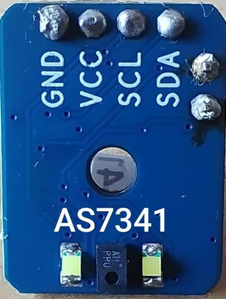
Pin Configuration and Descriptions
The AS7341 sensor has a 20-pin layout. Below is a table summarizing the key pins:
| Pin Name | Type | Description |
|---|---|---|
| VDD | Power | Main power supply (3.3V). |
| VDD_IO | Power | I/O voltage supply (1.8V). |
| GND | Ground | Ground connection. |
| SDA | I²C Data | Serial data line for I²C communication. |
| SCL | I²C Clock | Serial clock line for I²C communication. |
| INT | Output | Interrupt output for event signaling. |
| GPIO1 | Input/Output | General-purpose I/O pin. |
| GPIO2 | Input/Output | General-purpose I/O pin. |
| LED | Output | LED driver output for external illumination. |
| NC | - | No connection (leave unconnected). |
Usage Instructions
The AS7341 sensor is straightforward to integrate into a circuit, thanks to its I²C interface. Below are the steps and considerations for using the sensor effectively.
How to Use the Component in a Circuit
- Power Supply: Connect the VDD pin to a 3.3V power source and the VDD_IO pin to a 1.8V source. Ensure proper decoupling capacitors are placed near the power pins.
- I²C Communication: Connect the SDA and SCL pins to the corresponding I²C lines of your microcontroller. Use pull-up resistors (typically 4.7 kΩ) on both lines.
- Interrupt Pin: Optionally, connect the INT pin to a GPIO pin on your microcontroller to handle interrupts.
- LED Driver: If external illumination is required, connect an LED to the LED pin with an appropriate current-limiting resistor.
- Initialization: Configure the sensor via I²C commands to set the desired measurement mode and gain settings.
Important Considerations and Best Practices
- I²C Address: The default I²C address of the AS7341 is
0x39. Ensure no address conflicts on the I²C bus. - Calibration: For accurate measurements, calibrate the sensor in the target environment.
- Ambient Light: Avoid direct exposure to intense light sources, as this may saturate the sensor.
- Temperature Effects: Operate the sensor within the specified temperature range to maintain accuracy.
Example Code for Arduino UNO
Below is an example of how to interface the AS7341 with an Arduino UNO using the Wire library:
#include <Wire.h>

#define AS7341_I2C_ADDRESS 0x39 // Default I²C address of the AS7341

void setup() {
  Wire.begin(); // Initialize I²C communication
  Serial.begin(9600); // Initialize serial communication for debugging

  // Initialize the AS7341
  if (!initializeAS7341()) {
    Serial.println("AS7341 initialization failed!");
    while (1); // Halt execution if initialization fails
  }
  Serial.println("AS7341 initialized successfully.");
}

void loop() {
  // Read and print light intensity data
  uint16_t channelData = readChannelData(0); // Example: Read channel 0
  Serial.print("Channel 0 Data: ");
  Serial.println(channelData);

  delay(1000); // Wait 1 second before the next reading
}

bool initializeAS7341() {
  Wire.beginTransmission(AS7341_I2C_ADDRESS);
  Wire.write(0x80); // Example: Write to a control register
  Wire.write(0x01); // Example: Enable the sensor
  return (Wire.endTransmission() == 0); // Check for successful transmission
}

uint16_t readChannelData(uint8_t channel) {
  Wire.beginTransmission(AS7341_I2C_ADDRESS);
  Wire.write(0x94 + channel * 2); // Example: Address of the channel data register
  Wire.endTransmission();

  Wire.requestFrom(AS7341_I2C_ADDRESS, 2); // Request 2 bytes of data
  uint16_t data = Wire.read(); // Read the first byte
  data |= (Wire.read() << 8); // Read the second byte and combine
  return data;
}
Troubleshooting and FAQs
Common Issues and Solutions
Sensor Not Responding on I²C Bus
- Cause: Incorrect wiring or missing pull-up resistors.
- Solution: Verify the connections and ensure pull-up resistors are present on SDA and SCL lines.
Inaccurate Measurements
- Cause: Improper calibration or environmental interference.
- Solution: Calibrate the sensor in the target environment and shield it from stray light sources.
Interrupts Not Triggering
- Cause: Interrupt pin not connected or configured.
- Solution: Ensure the INT pin is connected to a GPIO pin and properly configured in the microcontroller firmware.
High Power Consumption
- Cause: Sensor operating in continuous mode.
- Solution: Use low-power modes or reduce measurement frequency.
FAQs
Q: Can the AS7341 detect UV light?
- A: No, the AS7341 is designed for visible and near-infrared light detection (350 nm to 1000 nm).
Q: What is the maximum I²C speed supported?
- A: The AS7341 supports I²C speeds up to 1 MHz.
Q: Is the sensor compatible with 5V logic?
- A: No, the AS7341 operates at 1.8V for I/O. Use a level shifter if interfacing with 5V logic.
Q: Can I use the sensor outdoors?
- A: Yes, but ensure it is protected from extreme environmental conditions and direct sunlight.