
How to Use LED matrix 8x32 DOT: Examples, Pinouts, and Specs
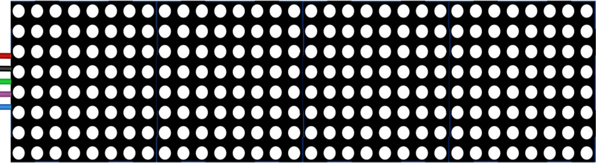
 Design with LED matrix 8x32 DOT in Cirkit Designer
Introduction
The AZDelivery MAX7219 8x32 LED Matrix is a versatile display module consisting of 256 individual LEDs arranged in 8 rows and 32 columns. This module is driven by the MAX7219 LED driver IC, which simplifies the control of the LEDs by reducing the number of required microcontroller pins. It is ideal for displaying scrolling text, animations, and simple graphics in applications such as digital signage, decorative lighting, and DIY electronics projects.
The module is compatible with popular microcontrollers like Arduino, Raspberry Pi, and ESP8266, making it a favorite among hobbyists and professionals alike.
Explore Projects Built with LED matrix 8x32 DOT
 Open Project in Cirkit Designer
 Open Project in Cirkit Designer
 Open Project in Cirkit Designer
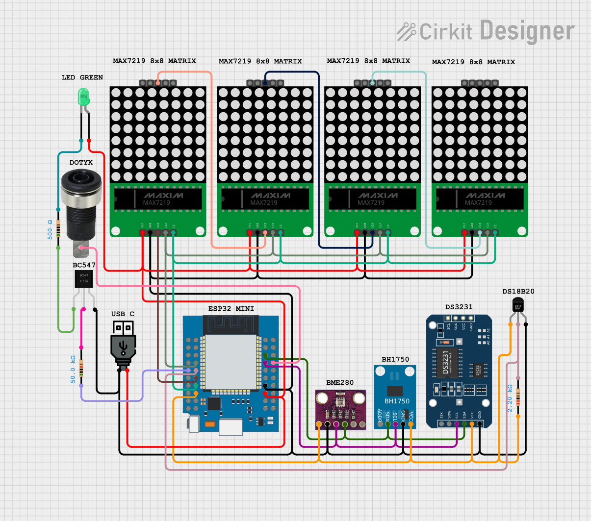 Open Project in Cirkit Designer
Explore Projects Built with LED matrix 8x32 DOT
Open Project in Cirkit DesignerOpen Project in Cirkit DesignerOpen Project in Cirkit DesignerOpen Project in Cirkit DesignerTechnical Specifications
Below are the key technical details of the AZDelivery MAX7219 8x32 LED Matrix:
| Parameter | Specification |
|---|---|
| Manufacturer | AZDelivery |
| Part ID | MAX7219 8x32 |
| LED Configuration | 8 rows x 32 columns (256 LEDs total) |
| Driver IC | MAX7219 |
| Operating Voltage | 5V DC |
| Operating Current | ~320mA (varies with brightness) |
| Communication Protocol | SPI (Serial Peripheral Interface) |
| Dimensions | 128mm x 32mm x 15mm |
Pin Configuration
The module has a 5-pin interface for connecting to a microcontroller. The pinout is as follows:
| Pin | Name | Description |
|---|---|---|
| 1 | VCC | Power supply input (5V DC) |
| 2 | GND | Ground connection |
| 3 | DIN | Serial data input (connect to microcontroller's MOSI pin) |
| 4 | CS | Chip select (active low, used to enable communication with the MAX7219 driver) |
| 5 | CLK | Clock input (connect to microcontroller's SCK pin) |
Usage Instructions
Connecting the LED Matrix to an Arduino UNO
To use the AZDelivery MAX7219 8x32 LED Matrix with an Arduino UNO, follow these steps:
Wiring: Connect the module to the Arduino UNO as shown below:
VCC→5VGND→GNDDIN→D11(MOSI)CS→D10CLK→D13(SCK)
Install the Required Library:
- Open the Arduino IDE.
- Go to Sketch > Include Library > Manage Libraries.
- Search for the "LedControl" library and install it.
Upload Example Code: Use the following example code to display scrolling text on the LED matrix:
// Include the LedControl library #include <LedControl.h> // Initialize the LedControl object // Parameters: DIN pin, CLK pin, CS pin, number of devices LedControl lc = LedControl(11, 13, 10, 1); void setup() { // Wake up the MAX7219 from power-saving mode lc.shutdown(0, false); // Set brightness level (0 = dim, 15 = bright) lc.setIntensity(0, 8); // Clear the display lc.clearDisplay(0); } void loop() { // Display scrolling text "HELLO" char message[] = "HELLO "; for (int i = 0; i < strlen(message); i++) { lc.setChar(0, 7 - i, message[i], false); delay(500); // Delay for smooth scrolling } }Note: The above code uses the
LedControllibrary to control the MAX7219. Ensure the library is installed before uploading the code.
Important Considerations
- Power Supply: Ensure the module is powered with a stable 5V DC source. Using a higher voltage may damage the LEDs or the MAX7219 IC.
- Current Requirements: The module can draw significant current, especially at higher brightness levels. If using multiple modules, consider using an external power supply.
- Daisy-Chaining: Multiple MAX7219 modules can be chained together to create larger displays. Connect the
DOUTpin of one module to theDINpin of the next.
Troubleshooting and FAQs
Common Issues
No Display Output:
- Verify all connections are secure and match the pinout table.
- Ensure the module is powered with 5V DC.
- Check that the
LedControllibrary is installed and included in your code.
Flickering LEDs:
- Reduce the brightness level using the
setIntensity()function. - Ensure the power supply can provide sufficient current.
- Reduce the brightness level using the
Incorrect or Garbled Output:
- Double-check the wiring, especially the
DIN,CS, andCLKconnections. - Ensure the correct number of devices is specified in the
LedControlobject initialization.
- Double-check the wiring, especially the
Module Overheating:
- Avoid running the module at maximum brightness for extended periods.
- Use a heat sink or active cooling if necessary.
FAQs
Q: Can I connect multiple LED matrices to a single Arduino?
A: Yes, you can daisy-chain multiple MAX7219 modules. Update the LedControl object initialization to reflect the total number of devices.
Q: How do I display custom patterns or animations?
A: Use the setRow() or setColumn() functions in the LedControl library to control individual rows or columns of LEDs.
Q: Is the module compatible with 3.3V microcontrollers?
A: The MAX7219 requires a 5V power supply, but the data pins are 3.3V logic-compatible. Use level shifters if needed for reliable operation.
Q: Can I use this module outdoors?
A: The module is not weatherproof. For outdoor use, enclose it in a waterproof housing.
By following this documentation, you can effectively integrate the AZDelivery MAX7219 8x32 LED Matrix into your projects and troubleshoot common issues with ease.