How to Use Renesas S7G2-SK: Examples, Pinouts, and Specs
Introduction
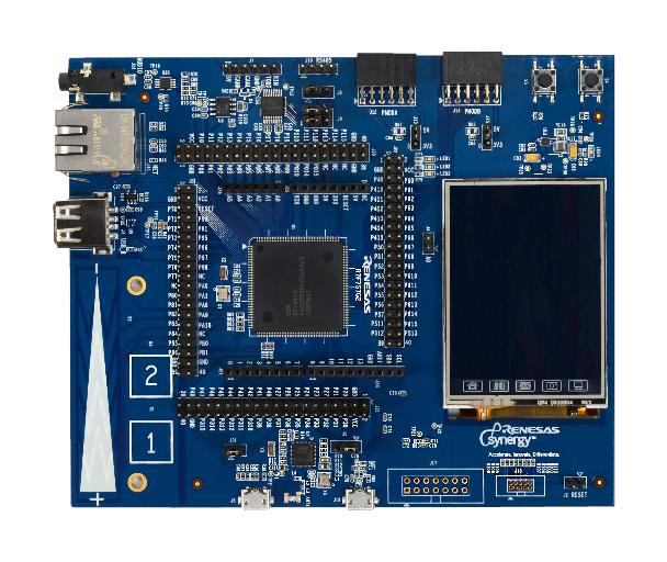
The Renesas S7G2-SK is a development kit built around the Renesas S7G2 microcontroller (Part ID: R7FS7G27H3A01CFC). This kit is designed to accelerate the prototyping and development of embedded systems, particularly for IoT, industrial automation, and graphical user interface (GUI)-based applications. The S7G2 microcontroller is part of the Renesas Synergy™ Platform, offering high performance, robust security, and extensive connectivity options.
Explore Projects Built with Renesas S7G2-SK


Explore Projects Built with Renesas S7G2-SK
Common Applications and Use Cases
- IoT devices and edge computing
- Industrial control systems
- Human-Machine Interfaces (HMIs)
- Wearable devices
- Home automation systems
- Prototyping for graphical and touch-based applications
Technical Specifications
Key Technical Details
| Parameter | Specification |
|---|---|
| Microcontroller | Renesas S7G2 (R7FS7G27H3A01CFC) |
| Core | ARM® Cortex®-M4 with Floating Point Unit (FPU) |
| Operating Frequency | Up to 240 MHz |
| Flash Memory | 4 MB |
| SRAM | 640 KB |
| Connectivity | USB, Ethernet, CAN, UART, SPI, I2C |
| Display Support | Integrated TFT-LCD controller with capacitive touch support |
| Power Supply | 5V via USB or external power source |
| Debugging Interface | JTAG/SWD |
| Operating Temperature | -40°C to +85°C |
| Dimensions | 120 mm x 80 mm |
Pin Configuration and Descriptions
The S7G2-SK development kit provides access to the microcontroller's pins via headers. Below is a summary of the key pin functions:
Power and Ground Pins
| Pin Name | Description |
|---|---|
| VCC | 5V power input |
| GND | Ground |
Communication Interfaces
| Pin Name | Description |
|---|---|
| TXD | UART Transmit |
| RXD | UART Receive |
| SCL | I2C Clock |
| SDA | I2C Data |
| MISO | SPI Master In, Slave Out |
| MOSI | SPI Master Out, Slave In |
| SCK | SPI Clock |
| CANH | CAN High |
| CANL | CAN Low |
GPIO and Other Pins
| Pin Name | Description |
|---|---|
| GPIOx | General Purpose Input/Output |
| ADCx | Analog-to-Digital Converter Pin |
| PWMx | Pulse Width Modulation Output |
Usage Instructions
How to Use the Component in a Circuit
Powering the Board:
- Connect the board to a 5V USB power source or an external power supply.
- Ensure the power source provides sufficient current for the peripherals in use.
Programming the Microcontroller:
- Use the onboard JTAG/SWD interface for debugging and programming.
- Alternatively, use the Renesas e2 Studio IDE with the Synergy Software Package (SSP) for development.
Connecting Peripherals:
- Use the GPIO pins for interfacing with external sensors, actuators, or other devices.
- Utilize the onboard communication interfaces (UART, SPI, I2C, CAN) for connecting to external modules.
Using the Display:
- The kit includes an integrated TFT-LCD controller. Connect a compatible display to the provided interface.
- Use the capacitive touch controller for touch-based applications.
Running Example Code:
- The Renesas Synergy Platform provides pre-configured example projects. Import these into e2 Studio to get started quickly.
Important Considerations and Best Practices
- Power Supply: Ensure the power supply is stable and within the specified voltage range to avoid damage to the board.
- Static Protection: Handle the board in an ESD-safe environment to prevent damage from static electricity.
- Peripheral Configuration: Configure the microcontroller's pins and peripherals correctly in software to avoid conflicts.
- Firmware Updates: Regularly update the firmware and development tools to access the latest features and bug fixes.
Example Code for Arduino UNO Integration
While the S7G2-SK is not directly compatible with Arduino, it can communicate with an Arduino UNO via UART. Below is an example of how to send data from the S7G2-SK to an Arduino UNO:
S7G2-SK UART Configuration (C Code)
#include "r_sci_uart.h" // Include UART driver header

sci_uart_instance_ctrl_t uart_ctrl;
sci_uart_cfg_t uart_cfg = {
    .channel = 0, // Use UART channel 0
    .baud_rate = 9600,
    .data_bits = SCI_UART_DATA_BITS_8,
    .parity = SCI_UART_PARITY_OFF,
    .stop_bits = SCI_UART_STOP_BITS_1,
    .p_callback = NULL, // No callback function
};

void uart_init(void) {
    // Initialize UART with the specified configuration
    R_SCI_UART_Open(&uart_ctrl, &uart_cfg);
}

void uart_send(const char *data) {
    // Send data over UART
    R_SCI_UART_Write(&uart_ctrl, (uint8_t *)data, strlen(data));
}
Arduino UNO UART Reception (Arduino Code)
void setup() {
  Serial.begin(9600); // Initialize UART at 9600 baud
}

void loop() {
  if (Serial.available() > 0) {
    // Read incoming data from UART
    String receivedData = Serial.readString();
    // Print the received data to the Serial Monitor
    Serial.println(receivedData);
  }
}
Troubleshooting and FAQs
Common Issues and Solutions
Board Not Powering On:
- Ensure the USB cable or external power supply is functioning correctly.
- Verify that the power source provides sufficient current.
Unable to Program the Microcontroller:
- Check the JTAG/SWD connections and ensure the debugger is properly configured.
- Verify that the correct microcontroller is selected in the development environment.
Peripherals Not Responding:
- Double-check the pin configurations in the firmware.
- Ensure the peripheral devices are powered and connected correctly.
Display Not Working:
- Confirm that the display is compatible with the S7G2-SK's TFT-LCD controller.
- Verify the display connections and initialization code.
FAQs
Q: Can I use the S7G2-SK for battery-powered applications?
A: Yes, the board can be powered by a battery, but ensure the voltage and current requirements are met.
Q: Is the S7G2-SK compatible with other Renesas Synergy microcontrollers?
A: The S7G2-SK is specifically designed for the S7G2 microcontroller, but the Synergy Software Package supports other Synergy MCUs.
Q: Where can I find example projects for the S7G2-SK?
A: Example projects are available in the Renesas Synergy Gallery and can be imported into the e2 Studio IDE.
Q: Can I use the S7G2-SK for real-time applications?
A: Yes, the ARM Cortex-M4 core with FPU and the Synergy Software Package make it suitable for real-time applications.