How to Use R4 minima: Examples, Pinouts, and Specs

Introduction
The R4 Minima is a resistor component designed to provide a minimum resistance value in electronic circuits. It ensures that the current flow is maintained at a specified level, preventing excessive current that could damage other components. This resistor is commonly used in current-limiting applications, voltage dividers, and as a pull-up or pull-down resistor in digital circuits.
Explore Projects Built with R4 minima
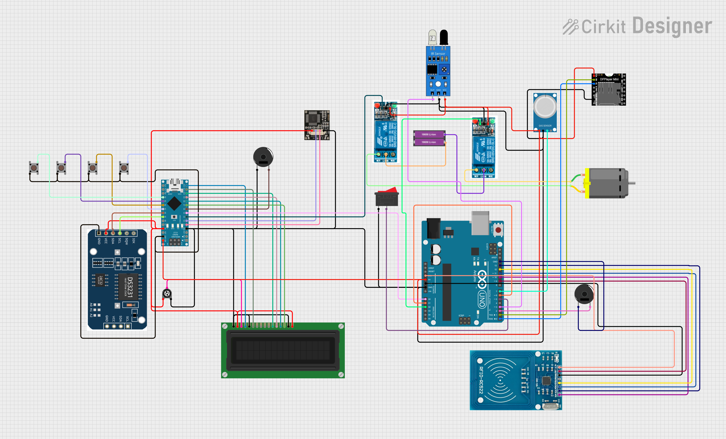
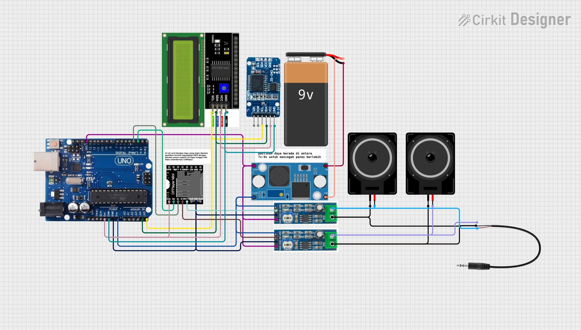
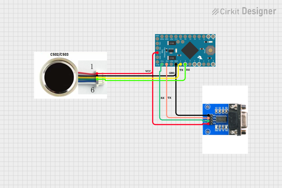

Explore Projects Built with R4 minima
Common Applications and Use Cases
- Current limiting in LED circuits
- Voltage divider networks
- Pull-up or pull-down resistors in microcontroller circuits
- Protection of sensitive components from overcurrent
- Stabilizing circuit operation by maintaining a minimum resistance
Technical Specifications
The R4 Minima is available in various resistance values and power ratings to suit different applications. Below are the general specifications:
| Parameter | Value |
|---|---|
| Resistance Range | 1 Ω to 10 kΩ |
| Tolerance | ±5% (standard) or ±1% (precision) |
| Power Rating | 0.125 W (1/8 W) to 1 W |
| Maximum Voltage Rating | 200 V |
| Temperature Coefficient | ±200 ppm/°C |
| Operating Temperature | -55°C to +155°C |
Pin Configuration and Descriptions
The R4 Minima is a two-terminal passive component. The pins are not polarized, meaning it can be connected in either orientation. Below is the pin description:
| Pin | Description |
|---|---|
| Pin 1 | Connects to one side of the circuit |
| Pin 2 | Connects to the other side of the circuit |
Usage Instructions
How to Use the R4 Minima in a Circuit
- Determine the Required Resistance Value: Calculate the resistance value needed for your application using Ohm's Law or circuit design requirements.
- Select the Appropriate Power Rating: Ensure the resistor's power rating exceeds the power it will dissipate in the circuit. Use the formula:
[ P = I^2 \times R ]
where (P) is power, (I) is current, and (R) is resistance. - Connect the Resistor: Place the R4 Minima in the circuit at the desired location. Since it is non-polarized, orientation does not matter.
- Verify the Circuit: Double-check connections and ensure the resistor is not overloaded.
Important Considerations and Best Practices
- Avoid Overheating: Ensure the resistor operates within its power rating to prevent damage or failure.
- Use Precision Resistors for Critical Applications: For circuits requiring high accuracy, choose R4 Minima resistors with a ±1% tolerance.
- Check for Voltage Ratings: Ensure the resistor's voltage rating is not exceeded in high-voltage circuits.
- Use in Series or Parallel: Combine resistors in series or parallel to achieve non-standard resistance values or higher power ratings.
Example: Using R4 Minima with an Arduino UNO
Below is an example of using the R4 Minima as a current-limiting resistor for an LED connected to an Arduino UNO:
// Example: LED with current-limiting resistor using Arduino UNO

const int ledPin = 9; // Pin connected to the LED
const int resistorValue = 220; // R4 Minima resistor value in ohms

void setup() {
  pinMode(ledPin, OUTPUT); // Set the LED pin as an output
}

void loop() {
  digitalWrite(ledPin, HIGH); // Turn the LED on
  delay(1000); // Wait for 1 second
  digitalWrite(ledPin, LOW); // Turn the LED off
  delay(1000); // Wait for 1 second
}

// Note: The R4 Minima resistor (220 ohms) is used to limit the current
// through the LED. This prevents the LED from drawing excessive current
// and ensures safe operation.
Troubleshooting and FAQs
Common Issues and Solutions
Resistor Overheating:
- Cause: The resistor is dissipating more power than its rated capacity.
- Solution: Use a resistor with a higher power rating or reduce the current in the circuit.
Incorrect Resistance Value:
- Cause: The wrong resistor value was selected or installed.
- Solution: Double-check the resistor's color code or measure its resistance with a multimeter.
Circuit Not Functioning as Expected:
- Cause: The resistor may be open (damaged) or improperly connected.
- Solution: Test the resistor with a multimeter and verify all connections.
LED Not Lighting Up in Arduino Circuit:
- Cause: The resistor value is too high, limiting the current excessively.
- Solution: Use a lower resistance value, ensuring it still limits current to a safe level for the LED.
FAQs
Q: Can I use the R4 Minima in high-frequency circuits?
A: Yes, but ensure the resistor's parasitic inductance and capacitance are negligible for your application. For very high frequencies, consider specialized resistors.
Q: How do I calculate the required resistance for an LED circuit?
A: Use the formula:
[
R = \frac{V_{supply} - V_{LED}}{I_{LED}}
]
where (V_{supply}) is the supply voltage, (V_{LED}) is the LED's forward voltage, and (I_{LED}) is the desired current through the LED.
Q: Can I use multiple R4 Minima resistors in parallel?
A: Yes, combining resistors in parallel reduces the total resistance and increases the power-handling capacity. Use the formula:
[
R_{total} = \frac{1}{\frac{1}{R_1} + \frac{1}{R_2} + \dots}
]
By following this documentation, you can effectively use the R4 Minima resistor in your electronic projects.