
How to Use TRANSISTOR_NPN: Examples, Pinouts, and Specs
 Design with TRANSISTOR_NPN in Cirkit Designer
Introduction
The NPN transistor is a type of bipolar junction transistor (BJT) that allows current to flow from the collector to the emitter when a small current is applied to the base. It is one of the most commonly used transistors in electronic circuits due to its versatility and efficiency. NPN transistors are widely used for amplification, switching, and signal processing in various applications.
Explore Projects Built with TRANSISTOR_NPN
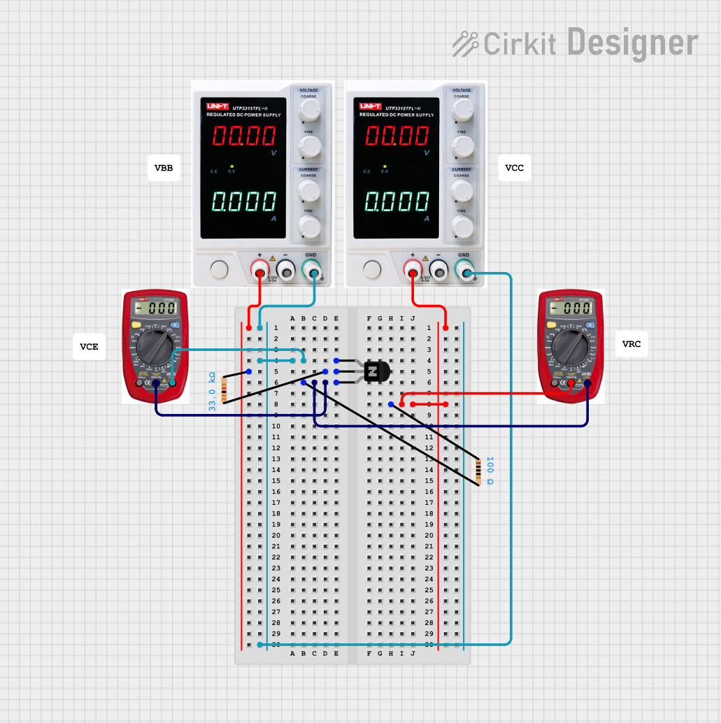 Open Project in Cirkit Designer
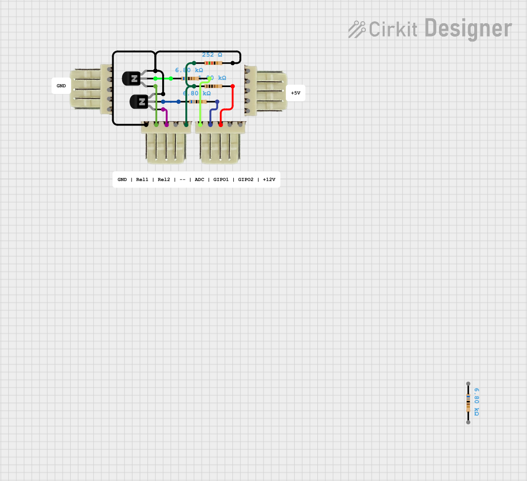 Open Project in Cirkit Designer
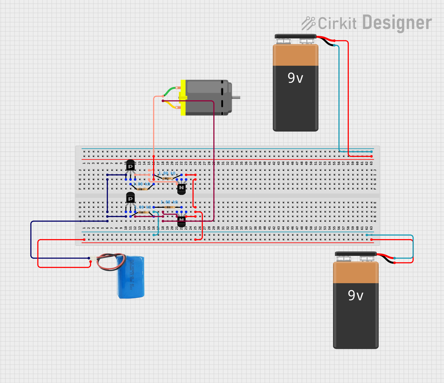 Open Project in Cirkit Designer
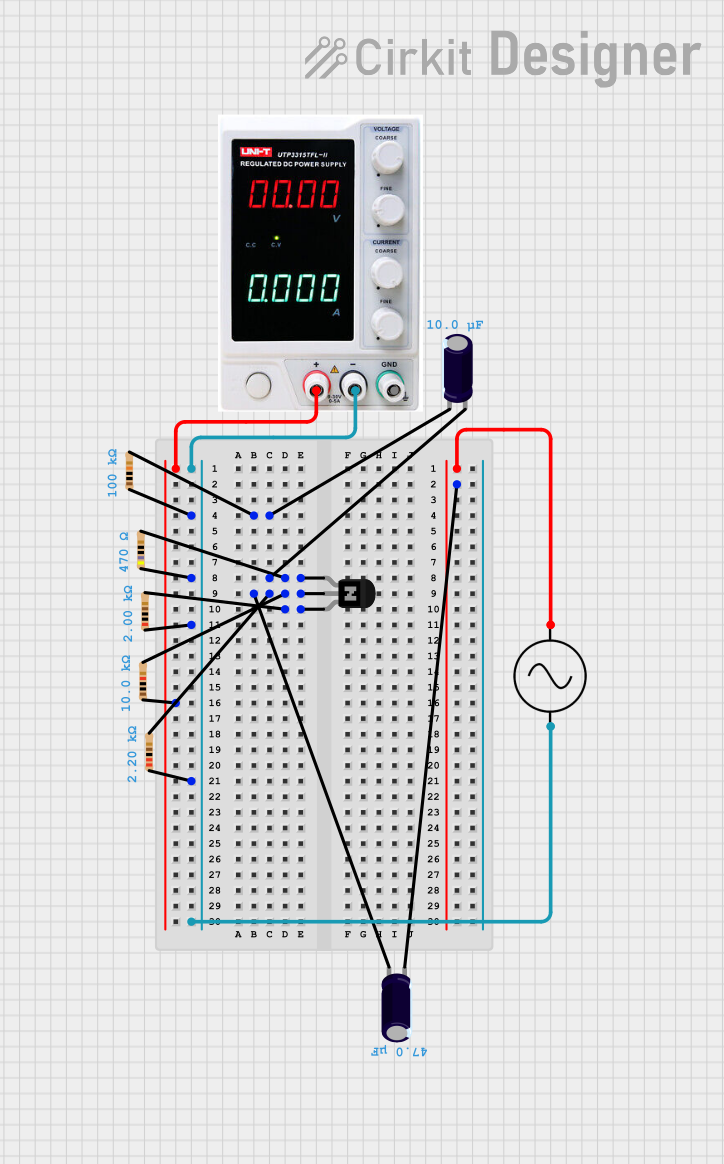 Open Project in Cirkit Designer
Explore Projects Built with TRANSISTOR_NPN
Open Project in Cirkit DesignerOpen Project in Cirkit DesignerOpen Project in Cirkit DesignerOpen Project in Cirkit DesignerCommon Applications and Use Cases
- Signal Amplification: Used in audio amplifiers, radio frequency amplifiers, and other signal processing circuits.
- Switching: Commonly used in digital circuits to control high-current loads such as motors, LEDs, and relays.
- Oscillators: Used in oscillator circuits for generating waveforms.
- Voltage Regulation: Found in power supply circuits for voltage stabilization.
Technical Specifications
Below are the general technical specifications for a standard NPN transistor (e.g., 2N2222 or BC547). Always refer to the specific datasheet of the transistor you are using for precise details.
| Parameter | Value |
|---|---|
| Type | NPN Bipolar Junction Transistor |
| Maximum Collector-Emitter Voltage (VCE) | 30V to 60V (varies by model) |
| Maximum Collector Current (IC) | 100mA to 800mA (varies by model) |
| Base-Emitter Voltage (VBE) | 0.6V to 0.7V |
| DC Current Gain (hFE) | 100 to 800 (varies by model) |
| Power Dissipation (PD) | 500mW to 1W |
| Operating Temperature Range | -55°C to +150°C |
| Package Type | TO-92, TO-220, etc. |
Pin Configuration
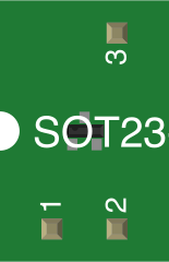
The pinout of an NPN transistor depends on its package type. Below is the pin configuration for a common TO-92 package.
| Pin Number | Pin Name | Description |
|---|---|---|
| 1 | Collector | Current flows into this terminal. |
| 2 | Base | Controls the transistor's operation. |
| 3 | Emitter | Current flows out of this terminal. |
Usage Instructions
How to Use the Component in a Circuit
- Identify the Pins: Determine the collector, base, and emitter pins using the datasheet or pinout diagram.
- Connect the Base Resistor: Use a resistor between the base and the control signal to limit the base current. The resistor value can be calculated using Ohm's law: [ R_b = \frac{V_{in} - V_{BE}}{I_B} ] where ( V_{in} ) is the input voltage, ( V_{BE} ) is the base-emitter voltage (typically 0.7V), and ( I_B ) is the desired base current.
- Connect the Load: Place the load (e.g., LED, motor) in series with the collector and the power supply.
- Power the Circuit: Apply the appropriate voltage to the collector and emitter terminals.
Important Considerations and Best Practices
- Base Current Limitation: Always use a resistor to limit the base current; excessive current can damage the transistor.
- Heat Dissipation: For high-power applications, ensure proper heat dissipation using a heatsink if necessary.
- Saturation Mode: For switching applications, ensure the transistor operates in saturation mode by providing sufficient base current (( I_B \geq I_C / h_{FE} )).
- Reverse Polarity: Avoid reversing the collector and emitter connections, as this can damage the transistor.
Example: Controlling an LED with an Arduino UNO
Below is an example of using an NPN transistor to control an LED with an Arduino UNO.
Circuit Diagram
- Collector: Connected to one terminal of the LED (with a current-limiting resistor in series).
- Emitter: Connected to ground.
- Base: Connected to an Arduino digital pin through a 1kΩ resistor.
Arduino Code
// Define the pin connected to the transistor's base
const int transistorBasePin = 9;

void setup() {
  // Set the transistor base pin as an output
  pinMode(transistorBasePin, OUTPUT);
}

void loop() {
  // Turn the LED on by applying HIGH to the transistor base
  digitalWrite(transistorBasePin, HIGH);
  delay(1000); // Keep the LED on for 1 second

  // Turn the LED off by applying LOW to the transistor base
  digitalWrite(transistorBasePin, LOW);
  delay(1000); // Keep the LED off for 1 second
}
Troubleshooting and FAQs
Common Issues and Solutions
Transistor Not Switching Properly
- Cause: Insufficient base current.
- Solution: Check the base resistor value and ensure it provides enough current to saturate the transistor.
Overheating
- Cause: Excessive collector current or inadequate heat dissipation.
- Solution: Verify the load current and ensure it is within the transistor's maximum rating. Use a heatsink if necessary.
LED Not Lighting Up
- Cause: Incorrect wiring or insufficient base drive.
- Solution: Double-check the circuit connections and ensure the base resistor is correctly calculated.
Transistor Always On or Off
- Cause: Faulty transistor or incorrect base signal.
- Solution: Test the transistor with a multimeter and verify the control signal from the microcontroller.
FAQs
Q: Can I use an NPN transistor to control AC loads?
A: No, NPN transistors are designed for DC circuits. For AC loads, consider using a TRIAC or relay.Q: How do I test if an NPN transistor is working?
A: Use a multimeter in diode mode. Check the base-emitter and base-collector junctions; they should behave like diodes (conduct in one direction only).Q: What happens if I exceed the maximum collector current?
A: Exceeding the maximum current can permanently damage the transistor. Always operate within the specified limits.
By following this documentation, you can effectively use an NPN transistor in your electronic projects.