How to Use Buck Boost Converter: Examples, Pinouts, and Specs
Introduction
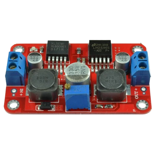
A Buck Boost Converter is a type of DC-DC converter that can step up (boost) or step down (buck) an input voltage to a desired output voltage level. This versatility makes it an essential component in power supply applications where the input voltage may vary but a stable output voltage is required. It is widely used in battery-powered devices, renewable energy systems, and embedded electronics.
Explore Projects Built with Buck Boost Converter


Explore Projects Built with Buck Boost Converter
Common Applications and Use Cases
- Battery-powered devices (e.g., smartphones, laptops, and portable gadgets)
- Renewable energy systems (e.g., solar panels and wind turbines)
- Automotive electronics
- LED drivers
- Embedded systems requiring stable voltage for microcontrollers and sensors
Technical Specifications
Below are the general technical specifications for a typical Buck Boost Converter. Note that specific models may vary, so always refer to the datasheet of the exact component you are using.
Key Technical Details
- Input Voltage Range: 2V to 36V (varies by model)
- Output Voltage Range: 1.2V to 24V (adjustable or fixed, depending on the model)
- Output Current: Up to 3A (varies by model)
- Efficiency: Up to 95% (depending on load and input/output conditions)
- Switching Frequency: 100kHz to 1MHz
- Operating Temperature: -40°C to +85°C
Pin Configuration and Descriptions
The pin configuration of a Buck Boost Converter IC (e.g., LM2577 or XL6009) typically includes the following:
| Pin Name | Description |
|---|---|
| VIN | Input voltage pin. Connect the input power source here. |
| GND | Ground pin. Connect to the ground of the circuit. |
| VOUT | Output voltage pin. Provides the regulated output voltage. |
| FB | Feedback pin. Used to set and stabilize the output voltage via a resistor divider. |
| EN (optional) | Enable pin. Used to turn the converter on or off (active high). |
| SW | Switch pin. Connects to the inductor and manages the switching operation. |
Usage Instructions
How to Use the Component in a Circuit
- Connect the Input Voltage: Attach the input voltage source to the VIN pin and ground to the GND pin.
- Set the Output Voltage: If the converter has an adjustable output, use a resistor divider network connected to the FB pin to set the desired output voltage. Refer to the datasheet for the formula to calculate resistor values.
- Connect the Load: Attach the load to the VOUT pin and ground.
- Add External Components: Include an inductor, input/output capacitors, and a diode as specified in the datasheet to ensure stable operation.
- Enable the Converter: If the converter has an EN pin, ensure it is pulled high to enable the device.
Important Considerations and Best Practices
- Inductor Selection: Choose an inductor with the appropriate current rating and inductance value to avoid saturation and ensure efficient operation.
- Capacitor Selection: Use low-ESR capacitors for input and output filtering to minimize voltage ripple.
- Thermal Management: Ensure adequate heat dissipation, especially for high-power applications. Use a heatsink or proper PCB layout for thermal management.
- Input Voltage Range: Ensure the input voltage stays within the specified range to avoid damaging the converter.
- Load Regulation: Test the converter with the intended load to verify stable output voltage.
Example: Using a Buck Boost Converter with Arduino UNO
Below is an example of connecting a Buck Boost Converter to an Arduino UNO to power it with a stable 5V output.
Circuit Connections
- Connect the input voltage source (e.g., a 9V battery) to the VIN and GND pins of the converter.
- Set the output voltage to 5V using the feedback resistor network.
- Connect the VOUT pin of the converter to the 5V pin of the Arduino UNO.
- Connect the GND pin of the converter to the GND pin of the Arduino UNO.
Arduino Code Example
// Example code to read a sensor powered by a Buck Boost Converter
// connected to an Arduino UNO. The converter provides a stable 5V output.

const int sensorPin = A0; // Analog pin connected to the sensor
int sensorValue = 0;      // Variable to store the sensor reading

void setup() {
  Serial.begin(9600); // Initialize serial communication at 9600 baud
  pinMode(sensorPin, INPUT); // Set the sensor pin as input
}

void loop() {
  sensorValue = analogRead(sensorPin); // Read the sensor value
  Serial.print("Sensor Value: ");
  Serial.println(sensorValue); // Print the sensor value to the Serial Monitor
  delay(1000); // Wait for 1 second before the next reading
}
Troubleshooting and FAQs
Common Issues and Solutions
No Output Voltage
- Cause: Incorrect wiring or insufficient input voltage.
- Solution: Double-check all connections and ensure the input voltage is within the specified range.
Excessive Heat
- Cause: Overloading the converter or insufficient cooling.
- Solution: Reduce the load current or improve heat dissipation using a heatsink or better airflow.
Output Voltage Instability
- Cause: Poor capacitor selection or incorrect feedback resistor values.
- Solution: Use low-ESR capacitors and verify the resistor values for the desired output voltage.
High Voltage Ripple
- Cause: Insufficient input/output filtering.
- Solution: Add or replace capacitors with higher capacitance or lower ESR.
FAQs
Q1: Can I use a Buck Boost Converter to power a microcontroller directly?
A1: Yes, as long as the output voltage is set to match the microcontroller's operating voltage (e.g., 3.3V or 5V) and the converter can supply sufficient current.
Q2: How do I calculate the feedback resistor values for an adjustable converter?
A2: Refer to the formula in the datasheet, typically:
[
V_{OUT} = V_{REF} \times \left(1 + \frac{R1}{R2}\right)
]
where ( V_{REF} ) is the reference voltage of the converter.
Q3: Can I use the Buck Boost Converter with an unregulated power source?
A3: Yes, the converter is designed to handle varying input voltages, but ensure the input voltage stays within the specified range.
Q4: What is the efficiency of a Buck Boost Converter?
A4: Efficiency typically ranges from 85% to 95%, depending on the load and input/output voltage conditions.