How to Use Busbar 250A 2P with 6 screws: Examples, Pinouts, and Specs
Introduction
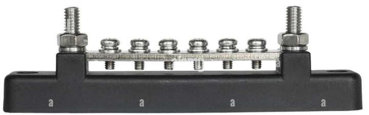
The Victron Busbar 250A 2P with 6 Screws is a high-quality electrical distribution component designed to handle up to 250A of current. It features two poles and six screw terminals, making it ideal for securely connecting multiple circuits in a compact and organized manner. This busbar is commonly used in power distribution systems, battery banks, and marine or automotive applications where reliable and efficient power distribution is critical.
Explore Projects Built with Busbar 250A 2P with 6 screws


Explore Projects Built with Busbar 250A 2P with 6 screws
Common Applications
- Power distribution in off-grid solar systems
- Battery bank connections in RVs, boats, and industrial setups
- High-current DC circuits in automotive and marine systems
- Electrical panels for organizing and distributing power
Technical Specifications
The following table outlines the key technical details of the Victron Busbar 250A 2P with 6 Screws:
| Specification | Details |
|---|---|
| Manufacturer | Victron |
| Rated Current | 250A |
| Number of Poles | 2 |
| Number of Screws | 6 |
| Voltage Rating | Up to 48V DC |
| Material | Tin-plated copper (conductive bar) |
| Insulation | High-strength plastic base |
| Mounting | Screw-mounted |
| Dimensions | 150mm x 45mm x 35mm (approx.) |
| Weight | 0.3 kg |
Pin Configuration and Descriptions
The busbar does not have traditional "pins" like an IC but instead features screw terminals for connections. Below is a description of the terminal layout:
| Terminal | Description |
|---|---|
| 1-3 | Positive pole screw terminals |
| 4-6 | Negative pole screw terminals |
| Mounting Holes | Used to secure the busbar to a surface |
Usage Instructions
How to Use the Busbar in a Circuit
Mounting the Busbar:
- Secure the busbar to a flat, non-conductive surface using the provided mounting holes.
- Ensure the busbar is positioned in a location with adequate ventilation to prevent overheating.
Connecting Wires:
- Strip the insulation from the wire ends to expose the conductive core.
- Attach the wires to the appropriate screw terminals (positive or negative poles) and tighten the screws securely.
- Use appropriately sized lugs or ferrules for high-current connections to ensure a reliable and safe connection.
Verify Connections:
- Double-check all connections to ensure they are tight and free of corrosion.
- Ensure that the wires are routed neatly to avoid accidental short circuits.
Testing:
- Power on the system and measure the voltage across the terminals to confirm proper operation.
Important Considerations and Best Practices
- Current Rating: Do not exceed the 250A current rating to avoid overheating or damage.
- Wire Gauge: Use wires with an appropriate gauge for the current being carried. For 250A, a wire gauge of 2/0 AWG or larger is recommended.
- Insulation: Ensure all connections are insulated to prevent accidental short circuits.
- Environment: Avoid exposing the busbar to moisture or corrosive environments unless additional protection is applied.
Example: Connecting to a Battery Bank
In a typical battery bank setup, the busbar can be used to distribute power from the batteries to multiple circuits. Below is an example of how to connect the busbar:
- Connect the positive terminals of the batteries to the positive pole of the busbar.
- Connect the negative terminals of the batteries to the negative pole of the busbar.
- Attach the load wires (e.g., inverter, charge controller) to the corresponding poles on the busbar.
Troubleshooting and FAQs
Common Issues and Solutions
Loose Connections:
- Issue: The screws may loosen over time due to vibration or thermal expansion.
- Solution: Periodically check and tighten all screws to ensure secure connections.
Overheating:
- Issue: The busbar becomes excessively hot during operation.
- Solution: Verify that the current does not exceed 250A and that the wire gauge is appropriate for the load.
Corrosion:
- Issue: Corrosion on the screw terminals or conductive bar.
- Solution: Clean the terminals with a contact cleaner and apply an anti-corrosion spray or dielectric grease.
Short Circuits:
- Issue: Accidental contact between the positive and negative poles.
- Solution: Ensure proper insulation of all connections and maintain adequate spacing between wires.
FAQs
Q: Can this busbar be used in AC circuits?
A: No, this busbar is designed for DC circuits with a voltage rating of up to 48V DC. It is not suitable for AC applications.
Q: What is the maximum wire size that can be connected to the busbar?
A: The busbar can accommodate wires up to 2/0 AWG, depending on the size of the lugs or ferrules used.
Q: Is the busbar waterproof?
A: No, the busbar is not waterproof. It should be installed in a dry, protected environment or enclosed in a waterproof housing if used in outdoor or marine applications.
Q: Can I connect more than six wires to the busbar?
A: No, the busbar is designed for six connections (three per pole). For additional connections, consider using a larger busbar or multiple busbars in parallel.
By following this documentation, users can safely and effectively integrate the Victron Busbar 250A 2P with 6 Screws into their electrical systems.