How to Use TJA1050 CAN transceiver: Examples, Pinouts, and Specs
Introduction
The TJA1050 is a high-speed CAN transceiver manufactured by Philips, designed to facilitate communication in Controller Area Network (CAN) applications. It acts as an interface between the CAN protocol controller and the physical CAN bus, ensuring reliable data transmission and reception. With support for data rates up to 1 Mbps, the TJA1050 is widely used in automotive and industrial environments where robust and efficient communication is essential.
Explore Projects Built with TJA1050 CAN transceiver

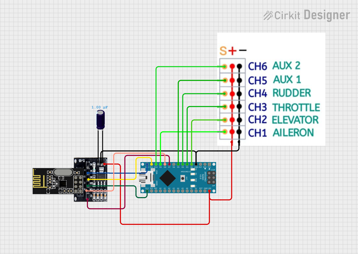
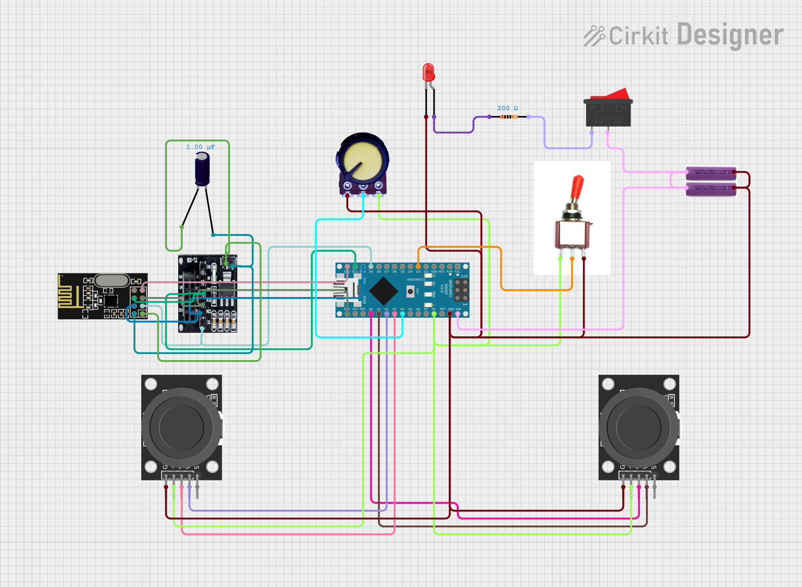
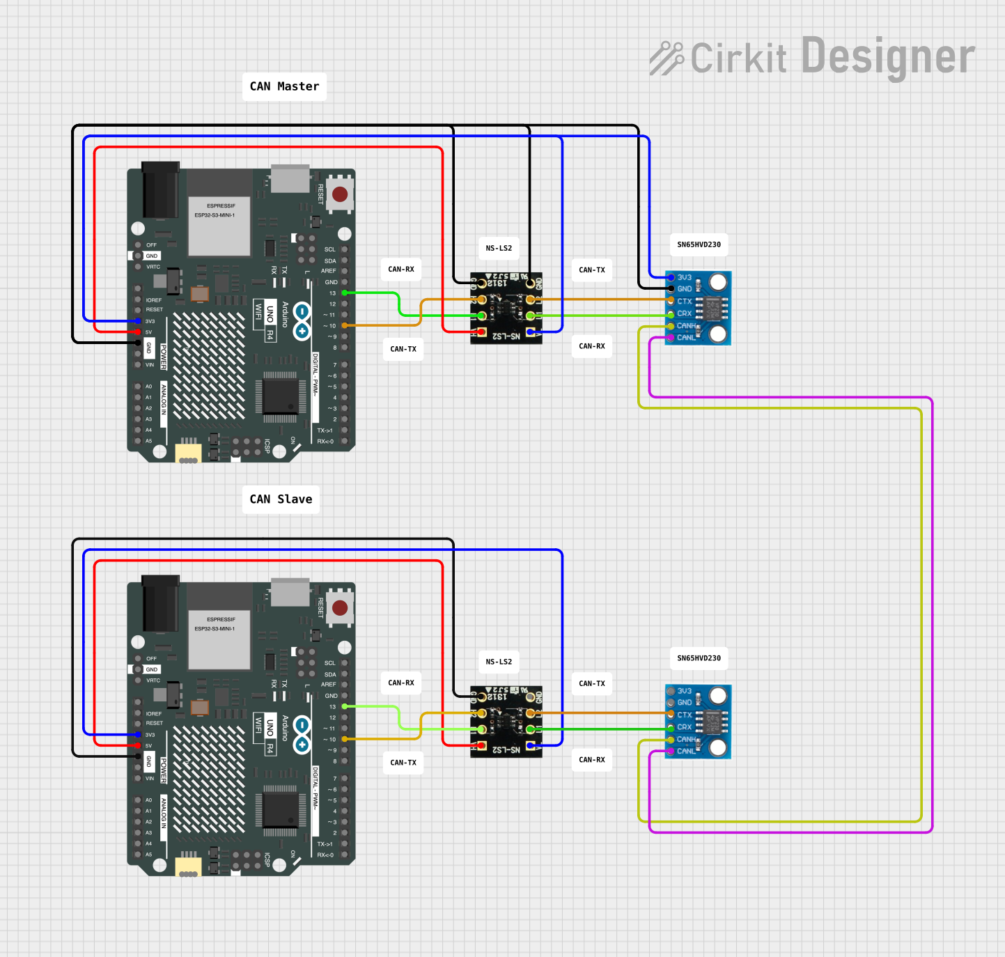
Explore Projects Built with TJA1050 CAN transceiver
Common Applications and Use Cases
- Automotive systems (e.g., engine control units, body control modules)
- Industrial automation and control
- Medical equipment
- Building automation
- Robotics and embedded systems requiring CAN communication
Technical Specifications
Key Technical Details
- Supply Voltage (Vcc): 4.5 V to 5.5 V
- Data Rate: Up to 1 Mbps
- Bus Voltage Range: -27 V to +40 V
- Standby Current: < 10 µA (low-power standby mode)
- Operating Temperature Range: -40°C to +125°C
- ESD Protection: ±6 kV (HBM, Human Body Model)
- Package Type: SO-8 (Small Outline) or DIP-8
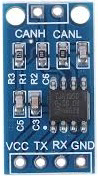
Pin Configuration and Descriptions
The TJA1050 is an 8-pin device. Below is the pinout and description:
| Pin Number | Pin Name | Description |
|---|---|---|
| 1 | TXD | Transmit Data Input: Connects to the CAN controller's transmit data output. |
| 2 | GND | Ground: Connect to the system ground. |
| 3 | Vcc | Supply Voltage: Connect to a 5 V power supply. |
| 4 | RXD | Receive Data Output: Outputs received data to the CAN controller. |
| 5 | Vref | Reference Voltage Output: Provides a reference voltage for the CAN controller. |
| 6 | CANL | CAN Low Line: Connects to the CAN bus low line. |
| 7 | CANH | CAN High Line: Connects to the CAN bus high line. |
| 8 | Rs | Slope Control: Configures the slope of the CAN signals for EMC optimization. |
Usage Instructions
How to Use the TJA1050 in a Circuit
Power Supply:
- Connect the Vcc pin to a regulated 5 V power supply.
- Connect the GND pin to the system ground.
CAN Bus Connection:
- Connect the CANH and CANL pins to the corresponding high and low lines of the CAN bus.
- Use a 120-ohm termination resistor between CANH and CANL at each end of the bus.
Controller Interface:
- Connect the TXD pin to the CAN controller's transmit data output.
- Connect the RXD pin to the CAN controller's receive data input.
Slope Control:
- Connect a resistor to the Rs pin to adjust the signal slope for electromagnetic compatibility (EMC).
- For high-speed operation, connect Rs directly to ground.
Reference Voltage:
- The Vref pin provides a reference voltage for the CAN controller. Ensure it is properly connected if required.
Important Considerations and Best Practices
- Ensure proper decoupling by placing a 100 nF capacitor close to the Vcc pin.
- Avoid long stubs on the CAN bus to minimize signal reflections.
- Use twisted-pair cables for the CANH and CANL lines to reduce electromagnetic interference (EMI).
- Ensure the CAN bus is properly terminated with 120-ohm resistors at both ends.
Example: Connecting TJA1050 to an Arduino UNO
Below is an example of how to connect the TJA1050 to an Arduino UNO for CAN communication:
Circuit Connections
- TJA1050 TXD → Arduino Digital Pin 2
- TJA1050 RXD → Arduino Digital Pin 3
- TJA1050 Vcc → Arduino 5V
- TJA1050 GND → Arduino GND
- TJA1050 CANH → CAN Bus High Line
- TJA1050 CANL → CAN Bus Low Line
- TJA1050 Rs → Ground (for high-speed mode)
Arduino Code Example
#include <SPI.h>
#include <mcp_can.h>

// Define CAN controller CS pin
#define CAN_CS 10

// Initialize CAN controller object
MCP_CAN CAN(CAN_CS);

void setup() {
  Serial.begin(115200);
  while (!Serial);

  // Initialize CAN bus at 500 kbps
  if (CAN.begin(MCP_ANY, 500000, MCP_8MHZ) == CAN_OK) {
    Serial.println("CAN bus initialized successfully!");
  } else {
    Serial.println("CAN bus initialization failed!");
    while (1);
  }

  // Set CAN bus to normal mode
  CAN.setMode(MCP_NORMAL);
  Serial.println("CAN bus set to normal mode.");
}

void loop() {
  // Send a test message
  byte data[8] = {0x01, 0x02, 0x03, 0x04, 0x05, 0x06, 0x07, 0x08};
  if (CAN.sendMsgBuf(0x100, 0, 8, data) == CAN_OK) {
    Serial.println("Message sent successfully!");
  } else {
    Serial.println("Error sending message.");
  }

  delay(1000); // Wait 1 second before sending the next message
}
Troubleshooting and FAQs
Common Issues and Solutions
No Communication on the CAN Bus:
- Verify that the CANH and CANL lines are properly connected and terminated with 120-ohm resistors.
- Check the power supply voltage (Vcc) and ensure it is within the specified range (4.5 V to 5.5 V).
High Error Rate:
- Ensure the Rs pin is configured correctly for the desired signal slope.
- Use twisted-pair cables for the CAN bus to reduce noise.
Device Overheating:
- Check for short circuits on the CANH and CANL lines.
- Ensure the supply voltage does not exceed 5.5 V.
No Output on RXD Pin:
- Verify that the TXD pin is receiving data from the CAN controller.
- Check the CAN bus for proper termination and signal integrity.
FAQs
Q: Can the TJA1050 operate at 3.3 V?
A: No, the TJA1050 requires a supply voltage between 4.5 V and 5.5 V. It is not compatible with 3.3 V systems without level shifting.
Q: What is the maximum cable length for the CAN bus?
A: The maximum cable length depends on the data rate. For example, at 1 Mbps, the maximum length is approximately 40 meters. For lower data rates, longer cable lengths are possible.
Q: How do I enable low-power standby mode?
A: To enable standby mode, configure the Rs pin with a high resistance or leave it floating. This reduces power consumption to less than 10 µA.
Q: Is the TJA1050 compatible with ISO 11898-2?
A: Yes, the TJA1050 complies with the ISO 11898-2 standard for high-speed CAN transceivers.