Cirkit Designer Logo
Cirkit Designer
Your all-in-one circuit design IDE
Home / 
Component Documentation

How to Use OpenSegment Serial Display - 20mm (Green): Examples, Pinouts, and Specs

Image of OpenSegment Serial Display - 20mm (Green)
Cirkit Designer LogoDesign with OpenSegment Serial Display - 20mm (Green) in Cirkit Designer

Introduction

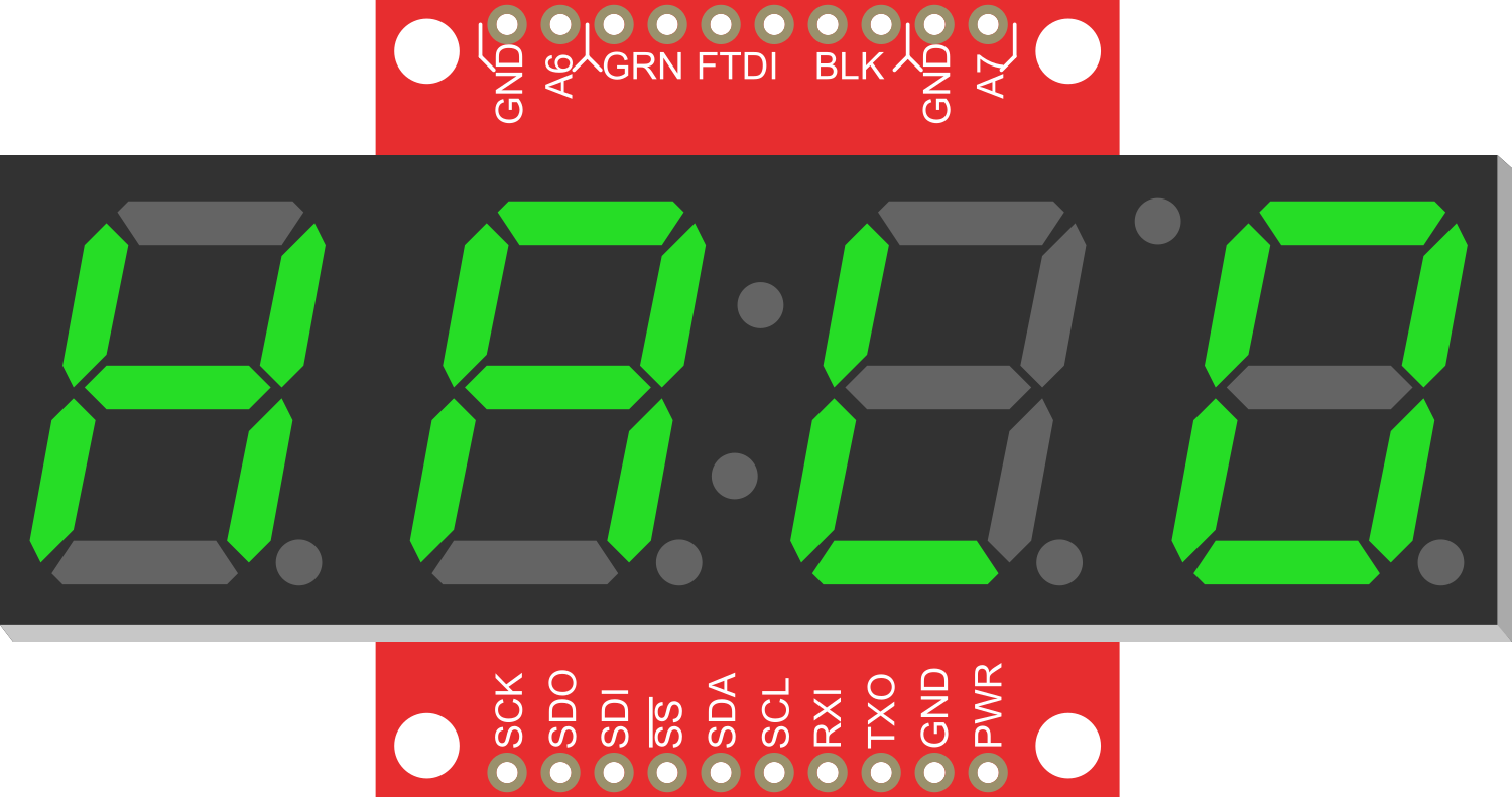
The OpenSegment Serial Display - 20mm (Green) is a versatile and easy-to-use seven-segment LED display module designed for displaying numeric and certain alphanumeric characters. Its bright green LEDs ensure good visibility in a variety of lighting conditions. This display is commonly used in digital clocks, timers, counters, and other projects where numerical data needs to be presented to the user.

Explore Projects Built with OpenSegment Serial Display - 20mm (Green)

Use Cirkit Designer to design, explore, and prototype these projects online. Some projects support real-time simulation. Click "Open Project" to start designing instantly!
ESP32-Controlled OLED Display with Button Interface
Image of RRR: A project utilizing OpenSegment Serial Display - 20mm (Green) in a practical application
This circuit features an ESP32 microcontroller connected to a 0.96" OLED display and a green button. The ESP32 powers the OLED display and communicates with it via I2C (with SDA and SCK connected to pins D21 and D22, respectively). The green button is connected to the ESP32's digital input pin D4, allowing it to trigger actions when pressed.
Cirkit Designer LogoOpen Project in Cirkit Designer
ESP32-Powered OLED Display Interface
Image of Display: A project utilizing OpenSegment Serial Display - 20mm (Green) in a practical application
This circuit connects an ESP32 microcontroller to a 0.96" OLED display via I2C communication protocol. The ESP32's pins D22 and D21 are used as the serial clock (SCK) and serial data (SDA) lines, respectively, to interface with the OLED's corresponding SCK and SDA pins. The OLED is powered by the 3.3V output from the ESP32, and both devices share a common ground. The embedded code initializes the display and prints 'Hello, ESP32!' on the screen.
Cirkit Designer LogoOpen Project in Cirkit Designer
ESP32-Controlled Multi-Display Interactive System with Pushbutton Inputs
Image of ORBS: A project utilizing OpenSegment Serial Display - 20mm (Green) in a practical application
This circuit consists of multiple GC9A01 display modules interfaced with an ESP32 microcontroller. The ESP32 controls the reset (RST), chip select (CS), data/command (DC), serial data (SDA), and serial clock (SCL) lines of each display, allowing for individual communication with each screen. Additionally, there are pushbuttons connected to the ESP32, which could be used for user input to control the displays or other functions within the circuit.
Cirkit Designer LogoOpen Project in Cirkit Designer
Arduino UNO Controlled Display and Servomotor System
Image of nim: A project utilizing OpenSegment Serial Display - 20mm (Green) in a practical application
This circuit features an Arduino UNO microcontroller that interfaces with a seven-segment display and controls a servomotor and two LEDs (red and green). A LM7805 voltage regulator with accompanying capacitors provides a stable 5V power supply. The circuit's functionality is determined by the embedded code, which is currently a placeholder for further development.
Cirkit Designer LogoOpen Project in Cirkit Designer

Explore Projects Built with OpenSegment Serial Display - 20mm (Green)

Use Cirkit Designer to design, explore, and prototype these projects online. Some projects support real-time simulation. Click "Open Project" to start designing instantly!
Image of RRR: A project utilizing OpenSegment Serial Display - 20mm (Green) in a practical application
ESP32-Controlled OLED Display with Button Interface
This circuit features an ESP32 microcontroller connected to a 0.96" OLED display and a green button. The ESP32 powers the OLED display and communicates with it via I2C (with SDA and SCK connected to pins D21 and D22, respectively). The green button is connected to the ESP32's digital input pin D4, allowing it to trigger actions when pressed.
Cirkit Designer LogoOpen Project in Cirkit Designer
Image of Display: A project utilizing OpenSegment Serial Display - 20mm (Green) in a practical application
ESP32-Powered OLED Display Interface
This circuit connects an ESP32 microcontroller to a 0.96" OLED display via I2C communication protocol. The ESP32's pins D22 and D21 are used as the serial clock (SCK) and serial data (SDA) lines, respectively, to interface with the OLED's corresponding SCK and SDA pins. The OLED is powered by the 3.3V output from the ESP32, and both devices share a common ground. The embedded code initializes the display and prints 'Hello, ESP32!' on the screen.
Cirkit Designer LogoOpen Project in Cirkit Designer
Image of ORBS: A project utilizing OpenSegment Serial Display - 20mm (Green) in a practical application
ESP32-Controlled Multi-Display Interactive System with Pushbutton Inputs
This circuit consists of multiple GC9A01 display modules interfaced with an ESP32 microcontroller. The ESP32 controls the reset (RST), chip select (CS), data/command (DC), serial data (SDA), and serial clock (SCL) lines of each display, allowing for individual communication with each screen. Additionally, there are pushbuttons connected to the ESP32, which could be used for user input to control the displays or other functions within the circuit.
Cirkit Designer LogoOpen Project in Cirkit Designer
Image of nim: A project utilizing OpenSegment Serial Display - 20mm (Green) in a practical application
Arduino UNO Controlled Display and Servomotor System
This circuit features an Arduino UNO microcontroller that interfaces with a seven-segment display and controls a servomotor and two LEDs (red and green). A LM7805 voltage regulator with accompanying capacitors provides a stable 5V power supply. The circuit's functionality is determined by the embedded code, which is currently a placeholder for further development.
Cirkit Designer LogoOpen Project in Cirkit Designer

Common Applications and Use Cases

  • Digital clocks and timers
  • Counters and scoreboards
  • Temperature or other environmental parameter displays
  • User interfaces for various electronic projects

Technical Specifications

Key Technical Details

  • Display Color: Green
  • Number of Digits: 4
  • Digit Height: 20mm
  • Operating Voltage: 3.3V to 7V
  • Maximum Current: 160mA at 5V
  • Communication: Serial (TTL) at 9600 or 19200 bps

Pin Configuration and Descriptions

Pin Number Name Description
1 VCC Power supply (3.3V to 7V)
2 GND Ground connection
3 RX Serial receive pin
4 TX Serial transmit pin (not used)

Usage Instructions

How to Use the Component in a Circuit

  1. Power Connection: Connect the VCC pin to a 3.3V to 7V power supply and the GND pin to the ground of your circuit.
  2. Serial Connection: Connect the RX pin to the TX pin of your microcontroller, such as an Arduino UNO.
  3. Initialization: Set up the serial communication on your microcontroller to match the baud rate of the display (default 9600 bps).

Important Considerations and Best Practices

  • Ensure that the power supply voltage does not exceed the maximum rating of 7V.
  • Avoid driving the display at its maximum current for extended periods to prevent overheating.
  • When using with a microcontroller, ensure that the serial communication settings match the display's requirements.

Example Code for Arduino UNO

#include <SoftwareSerial.h>

// Create a software serial port on pins 10 (RX) and 11 (TX)
SoftwareSerial openSegmentSerial(10, 11); // RX, TX

void setup() {
  // Start the software serial port at the baud rate of the display
  openSegmentSerial.begin(9600);
}

void loop() {
  // Send a command to clear the display
  openSegmentSerial.write(0x76); // Clear display command
  
  // Display a number with a decimal point
  openSegmentSerial.print("12.34");
  
  // Wait for 5 seconds
  delay(5000);
  
  // Display a different number
  openSegmentSerial.print("5678");
  
  // Wait for another 5 seconds
  delay(5000);
}

Note: The above code assumes that the display is set to the default baud rate of 9600 bps. If the baud rate has been changed, update the openSegmentSerial.begin(9600); line with the correct baud rate.

Troubleshooting and FAQs

Common Issues

  • Display Not Lighting Up: Check the power connections and ensure that the supply voltage is within the specified range.
  • Garbled or Incorrect Characters: Verify that the baud rate of the microcontroller's serial port matches the display's baud rate.
  • Display Flickering: Ensure that the power supply is stable and can provide sufficient current.

Solutions and Tips for Troubleshooting

  • Double-check all connections, especially the serial connection between the display and the microcontroller.
  • If you're experiencing communication issues, try using a different baud rate or check for any serial port conflicts.
  • For any persistent issues, consult the manufacturer's datasheet and support forums.

FAQs

Q: Can I use this display with a 3.3V microcontroller? A: Yes, the display can be powered with 3.3V, making it compatible with 3.3V microcontrollers.

Q: How do I change the baud rate of the display? A: The baud rate can typically be changed through a series of commands sent to the display. Refer to the manufacturer's datasheet for the specific commands.

Q: Can I display letters as well as numbers? A: Yes, the display can show certain alphanumeric characters. Refer to the character set in the manufacturer's datasheet for supported characters.