How to Use WCMCU-5102: Examples, Pinouts, and Specs
Introduction
The WCMCU-5102, manufactured by OTRONIC, is a microcontroller unit (MCU) specifically designed for wireless communication applications. It features low power consumption, integrated RF capabilities, and versatile I/O options, making it ideal for a wide range of IoT (Internet of Things) devices. This component is particularly suited for applications requiring efficient wireless data transmission, such as smart home devices, wearable technology, and industrial automation systems.
Explore Projects Built with WCMCU-5102


Explore Projects Built with WCMCU-5102
Common Applications and Use Cases
- Smart Home Devices: Wireless control of lighting, thermostats, and security systems.
- Wearable Technology: Fitness trackers, smartwatches, and health monitoring devices.
- Industrial Automation: Wireless sensor networks and actuator control.
- IoT Gateways: Communication hubs for connected devices.
- Remote Monitoring Systems: Environmental sensors and data loggers.
Technical Specifications
The WCMCU-5102 is a high-performance MCU with integrated wireless communication capabilities. Below are its key technical specifications:
General Specifications
| Parameter | Value |
|---|---|
| Manufacturer | OTRONIC |
| Part ID | audio-stereo-dac |
| Operating Voltage | 1.8V to 3.6V |
| Wireless Protocols | Wi-Fi (802.11 b/g/n), BLE 5.0 |
| Operating Frequency | 2.4 GHz |
| Flash Memory | 512 KB |
| RAM | 128 KB |
| GPIO Pins | 16 |
| Power Consumption | 10 µA (sleep mode), 15 mA (active mode) |
| Operating Temperature | -40°C to 85°C |
| Package Type | QFN-32 |
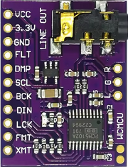
Pin Configuration and Descriptions
The WCMCU-5102 has a total of 32 pins. Below is the pin configuration:
| Pin Number | Pin Name | Description |
|---|---|---|
| 1 | VDD | Power supply (1.8V to 3.6V) |
| 2 | GND | Ground |
| 3 | RF_IN | RF input for wireless communication |
| 4 | RF_OUT | RF output for wireless communication |
| 5 | GPIO0 | General-purpose I/O pin |
| 6 | GPIO1 | General-purpose I/O pin |
| 7 | GPIO2 | General-purpose I/O pin |
| 8 | GPIO3 | General-purpose I/O pin |
| 9 | UART_TX | UART transmit pin |
| 10 | UART_RX | UART receive pin |
| 11 | I2C_SCL | I2C clock line |
| 12 | I2C_SDA | I2C data line |
| 13 | SPI_MOSI | SPI master-out, slave-in |
| 14 | SPI_MISO | SPI master-in, slave-out |
| 15 | SPI_CLK | SPI clock |
| 16 | SPI_CS | SPI chip select |
| 17-32 | Reserved | Reserved for future use or custom I/O |
Usage Instructions
The WCMCU-5102 is versatile and can be integrated into various circuits. Below are the steps and best practices for using this component:
Basic Circuit Setup
- Power Supply: Connect the VDD pin to a stable power source (1.8V to 3.6V) and the GND pin to ground.
- Wireless Communication: Use the RF_IN and RF_OUT pins for antenna connections to enable wireless communication.
- GPIO Configuration: Configure the GPIO pins as needed for sensors, actuators, or other peripherals.
- Communication Protocols:
- Use the UART_TX and UART_RX pins for serial communication.
- Use the I2C_SCL and I2C_SDA pins for I2C communication.
- Use the SPI_MOSI, SPI_MISO, SPI_CLK, and SPI_CS pins for SPI communication.
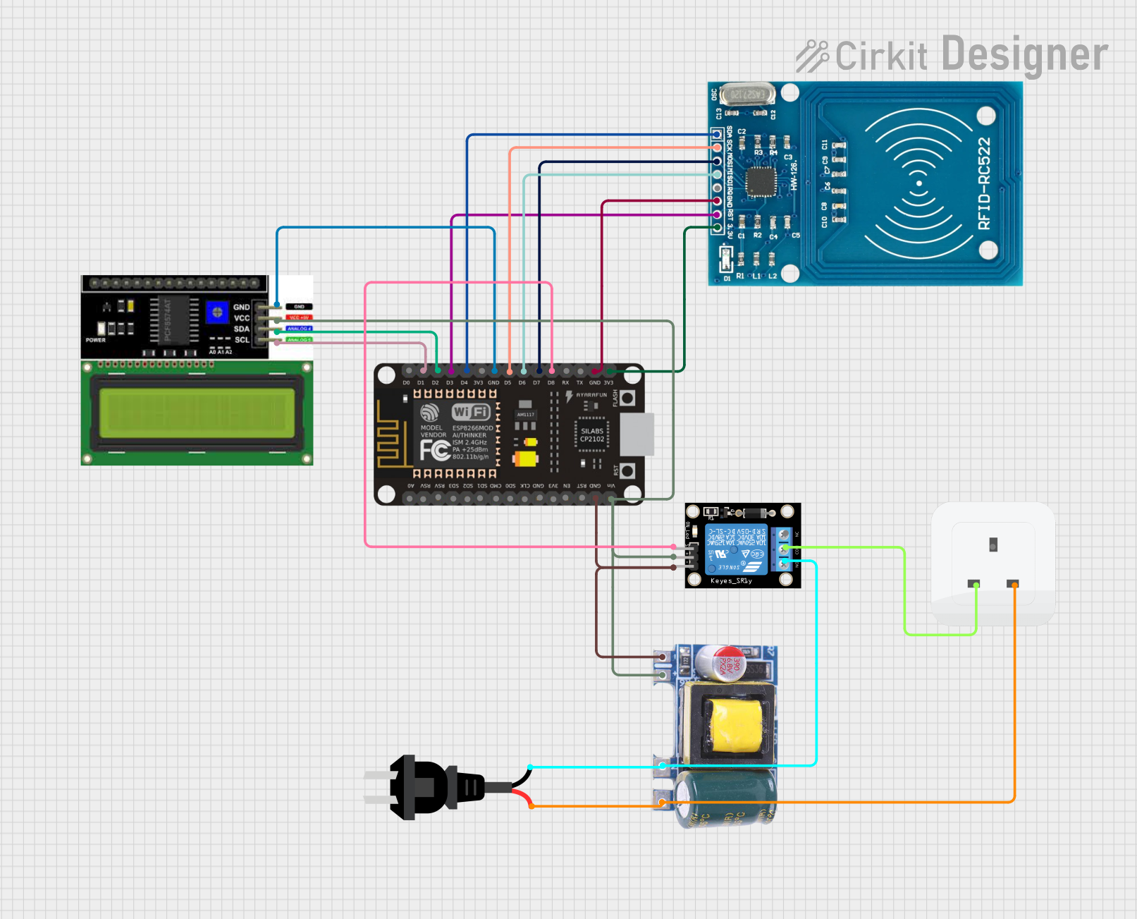
Example: Connecting to an Arduino UNO
The WCMCU-5102 can be interfaced with an Arduino UNO for wireless communication. Below is an example of how to set up the connection and code:
Wiring
- Connect the VDD pin of the WCMCU-5102 to the 3.3V pin of the Arduino.
- Connect the GND pin of the WCMCU-5102 to the GND pin of the Arduino.
- Connect the UART_TX pin of the WCMCU-5102 to the RX pin of the Arduino.
- Connect the UART_RX pin of the WCMCU-5102 to the TX pin of the Arduino.
Arduino Code
#include <SoftwareSerial.h>

// Define WCMCU-5102 pins connected to Arduino
#define WCMCU_TX 2  // WCMCU-5102 UART_TX connected to Arduino pin 2
#define WCMCU_RX 3  // WCMCU-5102 UART_RX connected to Arduino pin 3

// Create a SoftwareSerial object for communication
SoftwareSerial WCMCU(WCMCU_RX, WCMCU_TX);

void setup() {
  // Initialize serial communication with the WCMCU-5102
  Serial.begin(9600);  // For debugging via Serial Monitor
  WCMCU.begin(9600);   // Communication with WCMCU-5102

  Serial.println("Initializing WCMCU-5102...");
  WCMCU.println("AT");  // Send an AT command to test communication
}

void loop() {
  // Check if data is available from the WCMCU-5102
  if (WCMCU.available()) {
    String data = WCMCU.readString();
    Serial.println("Received from WCMCU-5102: " + data);
  }

  // Send data to the WCMCU-5102
  if (Serial.available()) {
    String command = Serial.readString();
    WCMCU.println(command);
  }
}
Best Practices
- Use decoupling capacitors (e.g., 0.1 µF) near the VDD pin to stabilize the power supply.
- Ensure proper antenna design for optimal wireless performance.
- Avoid placing the WCMCU-5102 near high-frequency noise sources to minimize interference.
Troubleshooting and FAQs
Common Issues
No Response from the WCMCU-5102:
- Ensure the power supply voltage is within the specified range (1.8V to 3.6V).
- Verify the UART connections and baud rate settings.
Poor Wireless Performance:
- Check the antenna connection and placement.
- Avoid obstructions or interference from other wireless devices.
Overheating:
- Ensure the component is not exposed to temperatures beyond its operating range (-40°C to 85°C).
- Verify that the power supply is not exceeding the maximum current rating.
Solutions and Tips
- Use a logic level shifter if interfacing with 5V systems like the Arduino UNO.
- Test the RF functionality in an open area to ensure proper communication range.
- Update the firmware of the WCMCU-5102 if available from the manufacturer.
By following this documentation, users can effectively integrate the WCMCU-5102 into their projects and troubleshoot common issues with ease.