How to Use LM567 Tone decoder: Examples, Pinouts, and Specs
Introduction
The LM567 is a tone decoder integrated circuit (IC) designed to detect specific audio frequencies and output a signal when the desired frequency is present. Manufactured by Tone Decoder, the LM567 is widely used in applications such as remote control systems, tone detection, frequency monitoring, and audio signal processing. Its ability to precisely detect a target frequency makes it a versatile component in communication and signal processing circuits.
Explore Projects Built with LM567 Tone decoder
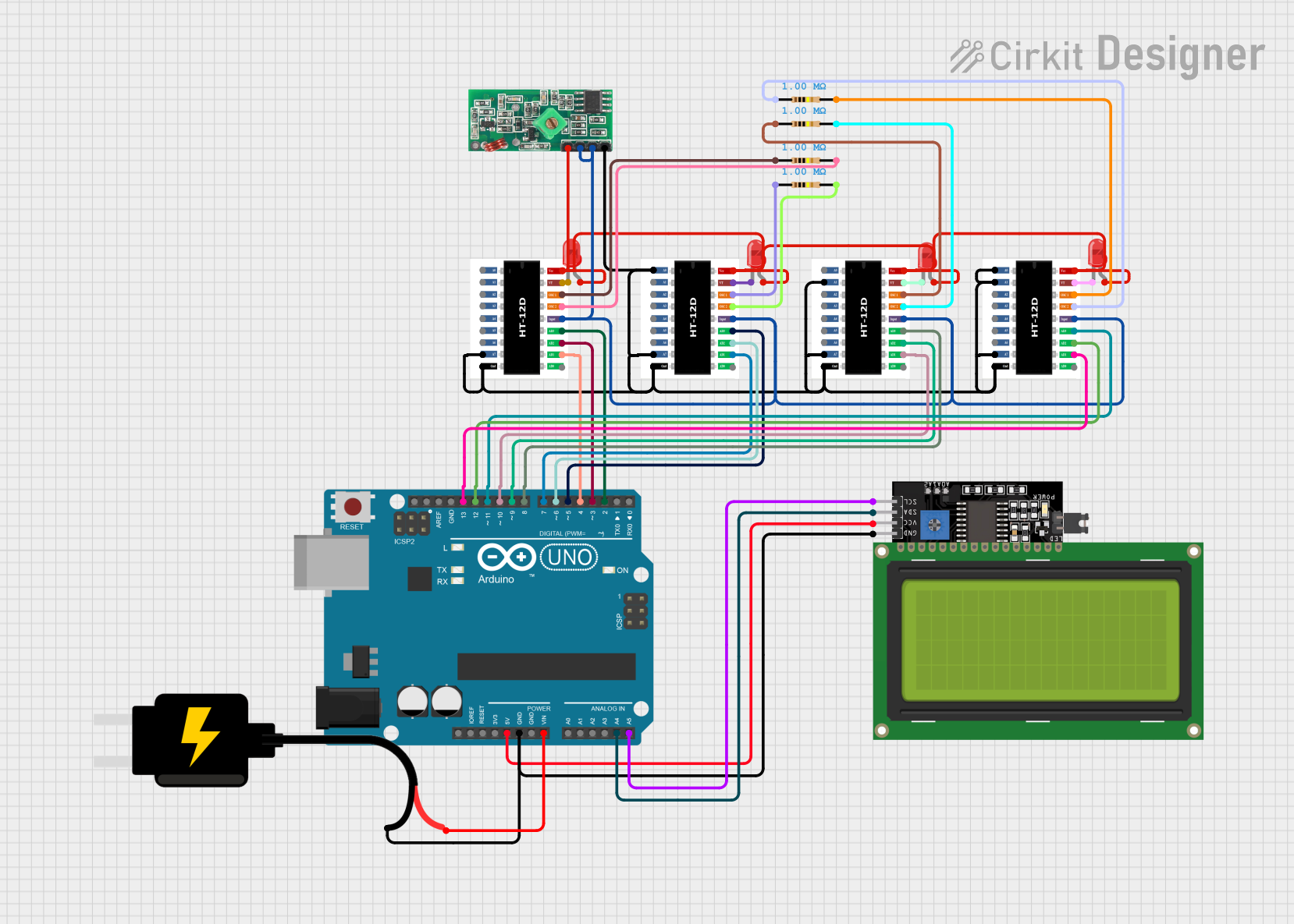
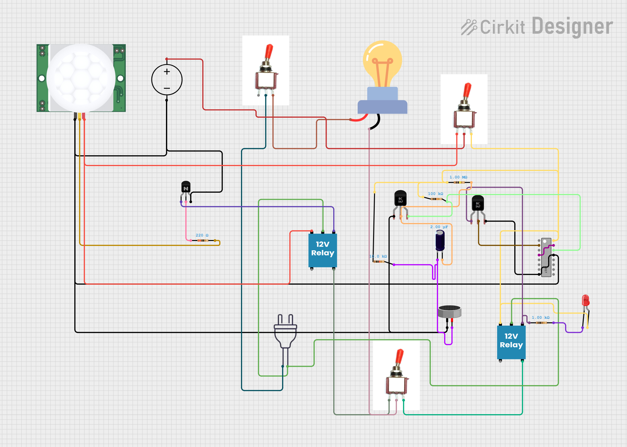
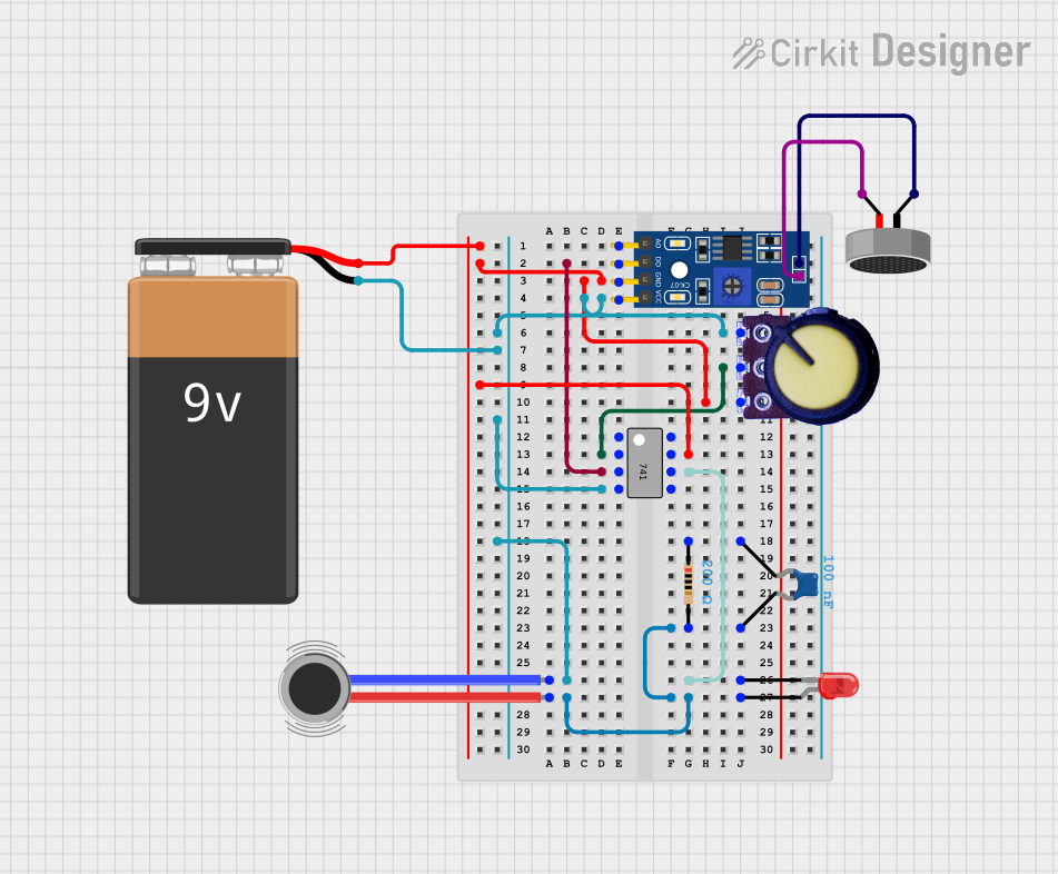
Explore Projects Built with LM567 Tone decoder
Technical Specifications
The LM567 is a highly reliable and efficient tone decoder IC with the following key specifications:
Key Technical Details
- Manufacturer Part ID: LM567
- Operating Voltage Range: 4.75V to 9V
- Quiescent Current: 2mA (typical) at 5V
- Input Impedance: 10MΩ (typical)
- Frequency Range: 0.01Hz to 500kHz
- Output Voltage (Low): 0.4V (max) at 10mA
- Output Voltage (High): Close to supply voltage
- Temperature Range: 0°C to 70°C
- Package Type: DIP-8 or SOIC-8
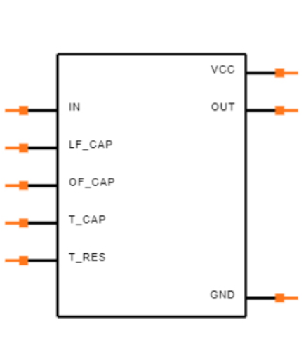
Pin Configuration and Descriptions
The LM567 is an 8-pin IC. Below is the pin configuration and description:
| Pin Number | Pin Name | Description |
|---|---|---|
| 1 | GND | Ground pin for the IC. Connect to the circuit's ground. |
| 2 | Input (IN) | Signal input pin. Connect the audio or frequency signal to this pin. |
| 3 | Filter Capacitor | Connect a capacitor to set the internal filter characteristics. |
| 4 | Timing Resistor | Connect a resistor to set the center frequency of the tone decoder. |
| 5 | Timing Capacitor | Connect a capacitor to set the center frequency of the tone decoder. |
| 6 | Output | Output pin. Goes low when the target frequency is detected. |
| 7 | Vcc | Positive supply voltage pin. Connect to the power supply (4.75V to 9V). |
| 8 | Loop Filter | Connect a capacitor to stabilize the phase-locked loop (PLL) operation. |
Usage Instructions
The LM567 is straightforward to use in a circuit. Follow these steps to integrate it into your design:
Determine the Target Frequency:
- Calculate the center frequency (
f_c) using the formula: [ f_c = \frac{1}{1.1 \cdot R_t \cdot C_t} ] where:- ( R_t ) is the timing resistor connected to Pin 4.
- ( C_t ) is the timing capacitor connected to Pin 5.
- Calculate the center frequency (
Set the Filter Capacitor:
- Connect a capacitor to Pin 3 to set the bandwidth of the internal filter. A typical value is 0.1µF.
Connect the Input Signal:
- Feed the audio or frequency signal to Pin 2. Ensure the signal amplitude is within the IC's input range.
Power the IC:
- Connect Pin 7 to a power supply (4.75V to 9V) and Pin 1 to ground.
Monitor the Output:
- The output at Pin 6 will go low when the target frequency is detected.
Example Circuit
Below is an example of how to connect the LM567 to detect a 1kHz tone:
- Target Frequency: 1kHz
- Timing Resistor (( R_t )): 10kΩ
- Timing Capacitor (( C_t )): 0.1µF
- Filter Capacitor: 0.1µF
Arduino UNO Example Code
The LM567 can be interfaced with an Arduino UNO to detect a specific frequency. Below is an example code:
// LM567 Tone Decoder Example with Arduino UNO
// This code monitors the LM567 output pin and turns on an LED when the target
// frequency is detected.

const int lm567OutputPin = 2; // LM567 output connected to Arduino pin 2
const int ledPin = 13;        // Onboard LED pin

void setup() {
  pinMode(lm567OutputPin, INPUT); // Set LM567 output pin as input
  pinMode(ledPin, OUTPUT);        // Set LED pin as output
  digitalWrite(ledPin, LOW);      // Turn off LED initially
}

void loop() {
  int toneDetected = digitalRead(lm567OutputPin); // Read LM567 output
  if (toneDetected == LOW) {
    // Target frequency detected, turn on LED
    digitalWrite(ledPin, HIGH);
  } else {
    // Target frequency not detected, turn off LED
    digitalWrite(ledPin, LOW);
  }
}
Important Considerations
- Ensure the input signal amplitude is within the IC's operating range to avoid damage.
- Use precise resistor and capacitor values to achieve accurate frequency detection.
- Decouple the power supply with a 0.1µF capacitor near the IC to reduce noise.
Troubleshooting and FAQs
Common Issues
No Output Signal:
- Check the power supply connections (Pin 7 and Pin 1).
- Verify the input signal is within the IC's operating range.
- Ensure the timing resistor and capacitor values are correct for the desired frequency.
False Triggering:
- Reduce noise in the input signal by adding a low-pass filter.
- Use a shielded cable for the input signal to minimize interference.
Output Always Low or High:
- Verify the target frequency calculation and component values.
- Check the filter capacitor (Pin 3) for proper bandwidth settings.
FAQs
Q1: Can the LM567 detect multiple frequencies simultaneously?
A1: No, the LM567 is designed to detect a single target frequency. For multiple frequencies, use multiple LM567 ICs.
Q2: What happens if the input signal amplitude is too high?
A2: Excessive input amplitude can cause distortion or damage the IC. Use a voltage divider or attenuator if needed.
Q3: Can the LM567 operate at frequencies above 500kHz?
A3: No, the LM567 is limited to a maximum frequency of 500kHz. For higher frequencies, consider alternative ICs.
By following this documentation, you can effectively use the LM567 tone decoder in your projects.