How to Use myTrafo: Examples, Pinouts, and Specs
Introduction
A myTrafo is a type of transformer designed to step up or step down voltage levels in electrical circuits. It plays a crucial role in ensuring efficient power transfer and electrical isolation between different sections of a circuit. By converting voltage levels, myTrafo enables compatibility between components with varying voltage requirements, making it an essential component in power supplies, audio systems, and industrial equipment.
Explore Projects Built with myTrafo

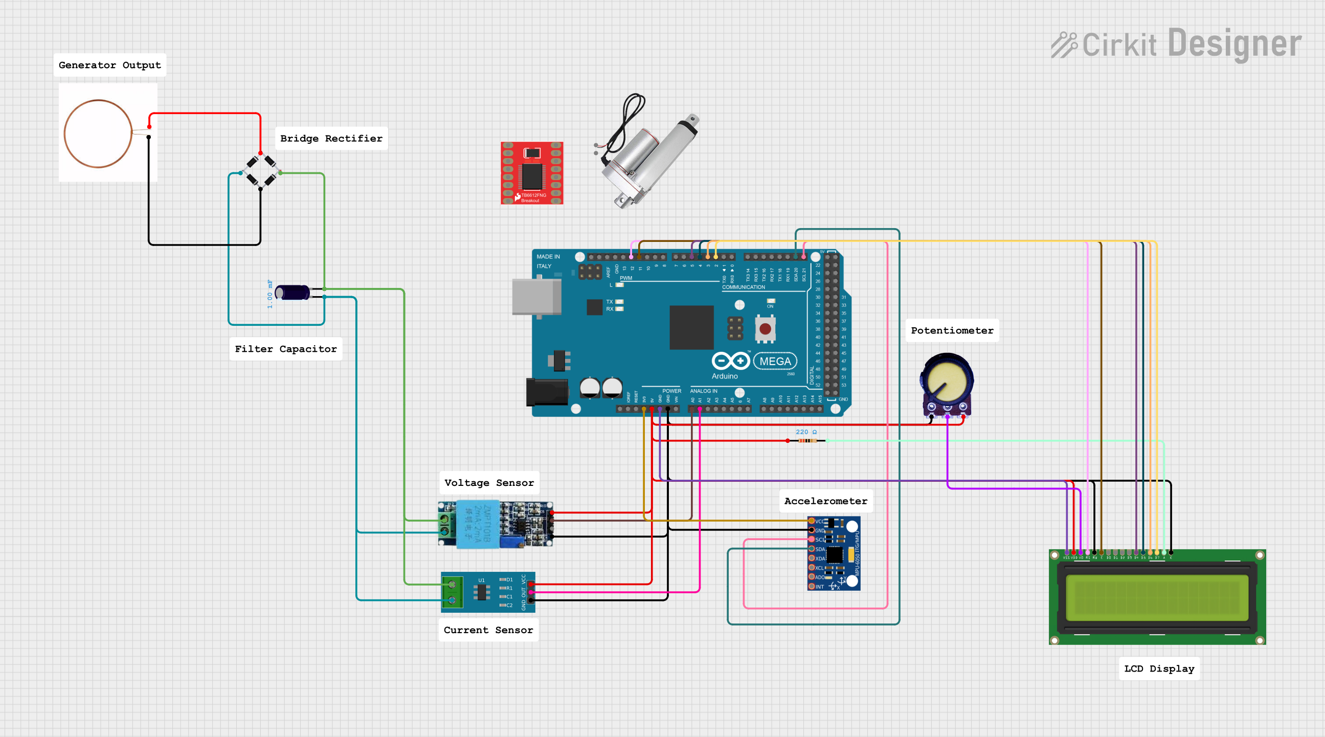


Explore Projects Built with myTrafo
Common Applications and Use Cases
- Power Supplies: Used to step down mains voltage to lower levels for electronic devices.
- Audio Systems: Provides impedance matching and isolation in audio circuits.
- Industrial Equipment: Steps up or steps down voltage for machinery and control systems.
- Renewable Energy Systems: Converts voltage levels in solar inverters and wind turbines.
- Isolation: Electrically isolates sensitive circuits to prevent interference or damage.
Technical Specifications
Below are the key technical details for the myTrafo transformer:
General Specifications
- Input Voltage Range: 110V AC to 240V AC
- Output Voltage Range: 5V AC to 24V AC (depending on model)
- Power Rating: 10W to 100W
- Frequency Range: 50Hz to 60Hz
- Efficiency: ≥ 90%
- Insulation Resistance: ≥ 100MΩ at 500V DC
- Dielectric Strength: 1500V AC for 1 minute
Pin Configuration and Descriptions
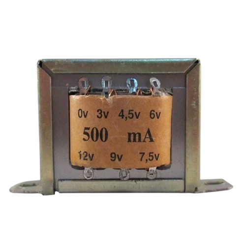
The myTrafo typically has four or more pins, depending on the model. Below is a standard pinout:
| Pin Number | Label | Description |
|---|---|---|
| 1 | Primary Input 1 | Connects to the live wire of the AC mains input. |
| 2 | Primary Input 2 | Connects to the neutral wire of the AC mains input. |
| 3 | Secondary Output 1 | Provides the stepped-up or stepped-down AC voltage output. |
| 4 | Secondary Output 2 | Provides the complementary terminal for the AC voltage output. |
| 5 (optional) | Ground (GND) | Optional grounding pin for additional safety and noise reduction. |
Note: Always refer to the datasheet of your specific myTrafo model for exact pin configuration.
Usage Instructions
How to Use the myTrafo in a Circuit
- Determine Voltage Requirements: Identify the input and output voltage levels required for your application.
- Connect the Primary Side:
- Connect Pin 1 to the live wire of the AC mains.
- Connect Pin 2 to the neutral wire of the AC mains.
- Connect the Secondary Side:
- Use Pins 3 and 4 to connect the load circuit that requires the transformed voltage.
- Optional Grounding: If your myTrafo model includes a ground pin (Pin 5), connect it to the circuit ground for added safety.
- Test the Circuit: Power on the circuit and measure the output voltage to ensure it matches the expected value.
Important Considerations and Best Practices
- Safety First: Always handle the transformer with care when working with high voltages. Ensure the circuit is powered off during installation.
- Load Matching: Ensure the load connected to the secondary side does not exceed the transformer's power rating.
- Heat Dissipation: Provide adequate ventilation or heat sinks if the transformer operates at high power levels.
- Isolation: Use the transformer to isolate sensitive circuits from high-voltage sections to prevent damage or interference.
Example: Using myTrafo with an Arduino UNO
If you are using myTrafo to power an Arduino UNO, you can step down the mains voltage to 9V AC, rectify it to DC, and regulate it to 5V using a voltage regulator. Below is an example code to read the voltage level on the Arduino:
// Example code to read voltage level using Arduino UNO
// Ensure the transformer output is rectified and regulated to a safe DC voltage
// before connecting to the Arduino.

const int voltagePin = A0; // Pin A0 is used to read the voltage
float voltage = 0.0;

void setup() {
  Serial.begin(9600); // Initialize serial communication at 9600 baud
}

void loop() {
  int sensorValue = analogRead(voltagePin); // Read the analog input
  voltage = sensorValue * (5.0 / 1023.0);   // Convert to voltage (assuming 5V reference)

  // Print the voltage to the Serial Monitor
  Serial.print("Voltage: ");
  Serial.print(voltage);
  Serial.println(" V");

  delay(1000); // Wait for 1 second before the next reading
}
Warning: Ensure the voltage supplied to the Arduino is within its operating range (7-12V DC recommended for the barrel jack, or 5V DC for the 5V pin).
Troubleshooting and FAQs
Common Issues and Solutions
No Output Voltage:
- Cause: Incorrect wiring on the primary or secondary side.
- Solution: Double-check the connections and ensure the input voltage is within the specified range.
Overheating:
- Cause: Exceeding the transformer's power rating or poor ventilation.
- Solution: Reduce the load or improve airflow around the transformer.
Noise or Humming:
- Cause: Loose windings or electromagnetic interference.
- Solution: Secure the transformer and ensure proper grounding.
Voltage Drop Under Load:
- Cause: Load exceeds the transformer's capacity.
- Solution: Use a transformer with a higher power rating.
FAQs
Q: Can I use myTrafo for DC voltage?
A: No, myTrafo is designed for AC voltage. To use it with DC, you must first convert the DC to AC using an inverter.Q: How do I calculate the output current?
A: Divide the transformer's power rating (in watts) by the output voltage to estimate the maximum output current.Q: Is myTrafo safe to use with mains voltage?
A: Yes, but always follow safety guidelines and ensure proper insulation and grounding.Q: Can I use myTrafo in reverse?
A: Yes, many transformers can be used in reverse, but ensure the voltage and current ratings are suitable for your application.