How to Use ATTINY84A: Examples, Pinouts, and Specs
Introduction
The ATTINY84A is a low-power 8-bit microcontroller from Atmel's AVR family, designed for compact and efficient embedded applications. With its 14-pin configuration, 8KB of flash memory, and versatile peripherals, the ATTINY84A is ideal for projects requiring a small footprint and low power consumption. It supports a wide range of functionalities, including timers, analog-to-digital conversion (ADC), and pulse-width modulation (PWM).
Explore Projects Built with ATTINY84A


Explore Projects Built with ATTINY84A
Common Applications
- IoT devices and sensors
- Wearable electronics
- Small robotics and automation systems
- Battery-powered devices
- LED control and lighting systems
Technical Specifications
Key Technical Details
| Parameter | Value |
|---|---|
| Manufacturer | Atmel |
| Part Number | ATTINY84A-SSFR |
| Architecture | AVR 8-bit |
| Flash Memory | 8KB |
| SRAM | 512 bytes |
| EEPROM | 512 bytes |
| Operating Voltage | 1.8V to 5.5V |
| Maximum Clock Speed | 20 MHz |
| I/O Pins | 6 (configurable as digital or analog) |
| ADC Resolution | 10-bit |
| Timers | 2 (8-bit and 16-bit) |
| PWM Channels | 4 |
| Communication Interfaces | SPI, I²C, and USART |
| Package Type | SOIC-14 |
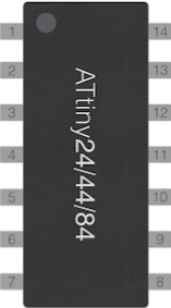
Pin Configuration and Descriptions
The ATTINY84A has 14 pins, each with specific functions. Below is the pinout description:
| Pin Number | Pin Name | Description |
|---|---|---|
| 1 | VCC | Power supply (1.8V to 5.5V) |
| 2 | PB0 | Digital I/O, ADC input, PWM output |
| 3 | PB1 | Digital I/O, ADC input, PWM output |
| 4 | PB3 | Digital I/O, ADC input, PWM output |
| 5 | PB2 | Digital I/O, ADC input, PWM output |
| 6 | PA7 | Digital I/O, ADC input |
| 7 | PA6 | Digital I/O, ADC input |
| 8 | PA5 | Digital I/O, ADC input |
| 9 | PA4 | Digital I/O, ADC input |
| 10 | PA3 | Digital I/O, ADC input |
| 11 | PA2 | Digital I/O, ADC input |
| 12 | PA1 | Digital I/O, ADC input |
| 13 | PA0 | Digital I/O, ADC input |
| 14 | GND | Ground |
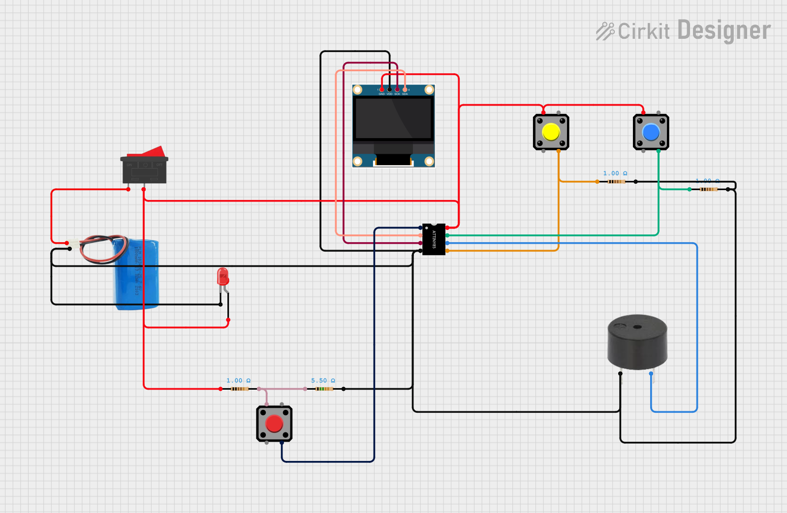
Usage Instructions
How to Use the ATTINY84A in a Circuit
- Power Supply: Connect the VCC pin to a power source (1.8V to 5.5V) and the GND pin to ground.
- Programming: Use an AVR programmer or an Arduino as an ISP (In-System Programmer) to upload code to the ATTINY84A.
- I/O Configuration: Configure the I/O pins as digital or analog inputs/outputs in your code.
- Peripherals: Utilize the built-in peripherals such as ADC, timers, and PWM for your application.
- Communication: Use SPI, I²C, or USART for interfacing with other devices.
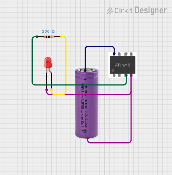
Important Considerations and Best Practices
- Decoupling Capacitors: Place a 0.1µF capacitor between VCC and GND to stabilize the power supply.
- Clock Source: The ATTINY84A can use an internal 8 MHz oscillator or an external crystal oscillator for higher precision.
- Pull-Up Resistors: Enable internal pull-up resistors for unused input pins to prevent floating states.
- Low Power Modes: Use sleep modes to reduce power consumption in battery-powered applications.
Example: Using ATTINY84A with Arduino UNO as ISP
Below is an example of programming the ATTINY84A using an Arduino UNO as an ISP:
Arduino UNO as ISP Setup
- Connect the Arduino UNO to your computer and upload the "ArduinoISP" sketch from the Arduino IDE.
- Wire the ATTINY84A to the Arduino UNO as follows:
- ATTINY84A Pin 1 (VCC) → Arduino 5V
- ATTINY84A Pin 14 (GND) → Arduino GND
- ATTINY84A Pin 4 (PB2) → Arduino Pin 10 (SS)
- ATTINY84A Pin 7 (PA6) → Arduino Pin 11 (MOSI)
- ATTINY84A Pin 8 (PA4) → Arduino Pin 12 (MISO)
- ATTINY84A Pin 9 (PA3) → Arduino Pin 13 (SCK)
Example Code
// Blink an LED connected to PB0 (Pin 2 on ATTINY84A)

// Define the LED pin
#define LED_PIN 0  // PB0 corresponds to digital pin 0 on ATTINY84A

void setup() {
  pinMode(LED_PIN, OUTPUT);  // Set PB0 as an output pin
}

void loop() {
  digitalWrite(LED_PIN, HIGH);  // Turn the LED on
  delay(500);                  // Wait for 500 milliseconds
  digitalWrite(LED_PIN, LOW);   // Turn the LED off
  delay(500);                  // Wait for 500 milliseconds
}
To upload the code:
- Select "ATTINY84A" as the board in the Arduino IDE.
- Choose the appropriate clock frequency (e.g., 8 MHz internal).
- Select "Arduino as ISP" as the programmer.
- Upload the sketch.
Troubleshooting and FAQs
Common Issues
The ATTINY84A is not responding to programming commands.
- Solution: Ensure the wiring between the programmer and the ATTINY84A is correct. Check for loose connections.
- Tip: Verify that the correct board and clock settings are selected in the Arduino IDE.
The microcontroller is not running the uploaded code.
- Solution: Check the power supply voltage and ensure it is within the operating range (1.8V to 5.5V).
- Tip: Confirm that the fuses are set correctly for the desired clock source.
Analog readings are unstable.
- Solution: Add a decoupling capacitor (e.g., 0.1µF) near the VCC and GND pins.
- Tip: Use an external reference voltage for the ADC if higher precision is required.
PWM output is not working as expected.
- Solution: Verify that the correct timer and pin are configured for PWM in the code.
- Tip: Check the datasheet for the specific timer and pin mappings.
FAQs
Can the ATTINY84A run at 3.3V?
- Yes, the ATTINY84A operates within a voltage range of 1.8V to 5.5V, making it compatible with 3.3V systems.
What is the maximum clock speed of the ATTINY84A?
- The maximum clock speed is 20 MHz when using an external crystal oscillator.
How many PWM channels are available?
- The ATTINY84A provides 4 PWM channels.
Can I use the ATTINY84A for I²C communication?
- Yes, the ATTINY84A supports I²C communication using the USI (Universal Serial Interface) module.
This concludes the documentation for the ATTINY84A. For further details, refer to the official datasheet provided by Atmel.