How to Use temp: Examples, Pinouts, and Specs
Introduction
The TEMP (Manufacturer Part ID: 123) is a temperature sensor manufactured by Bala. It is designed to measure ambient temperature and convert it into an electrical signal, making it suitable for a wide range of monitoring and control applications. This sensor is compact, reliable, and easy to integrate into various electronic systems.
Explore Projects Built with temp
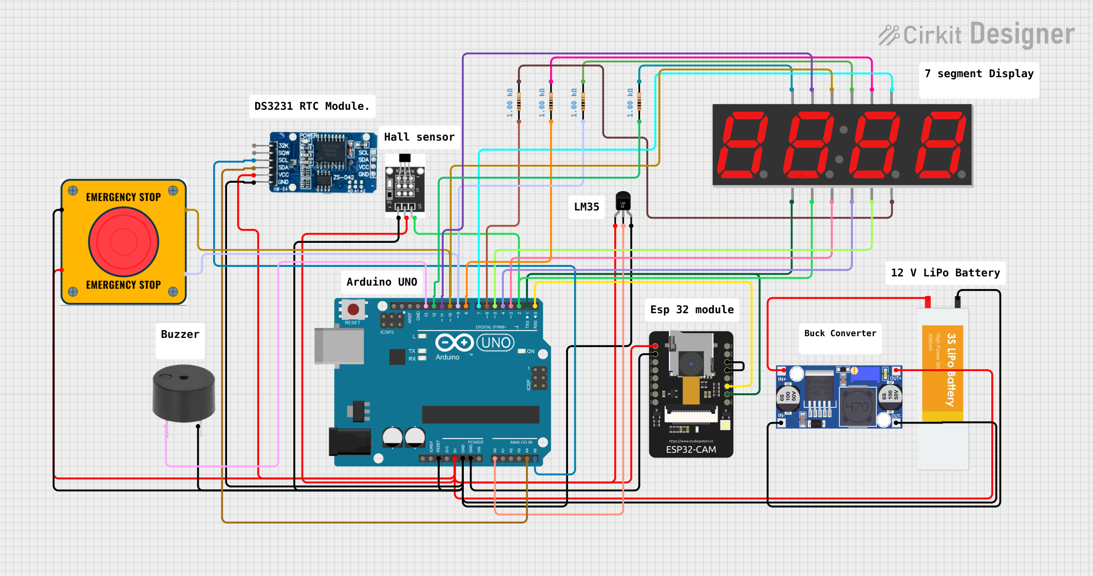

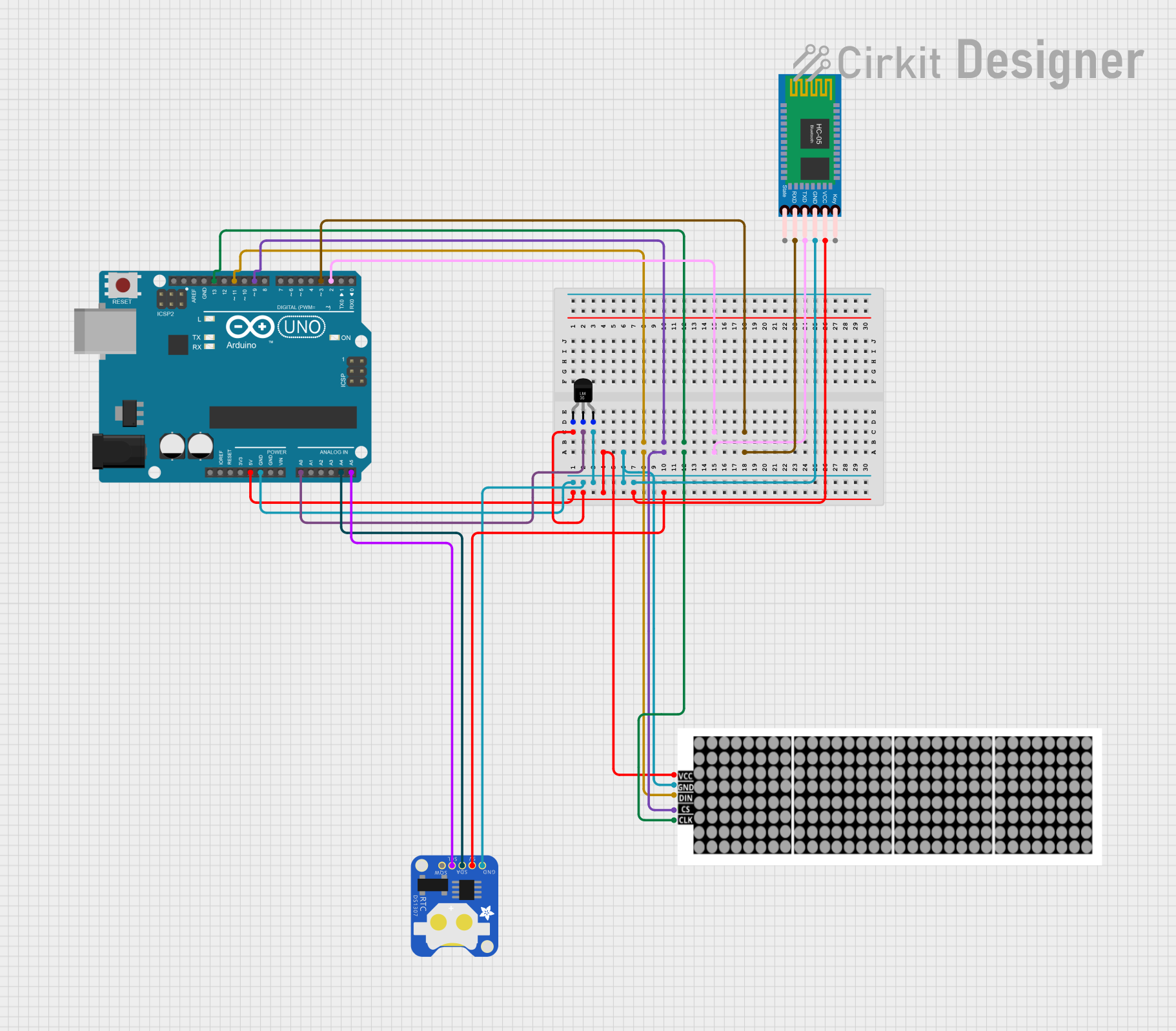
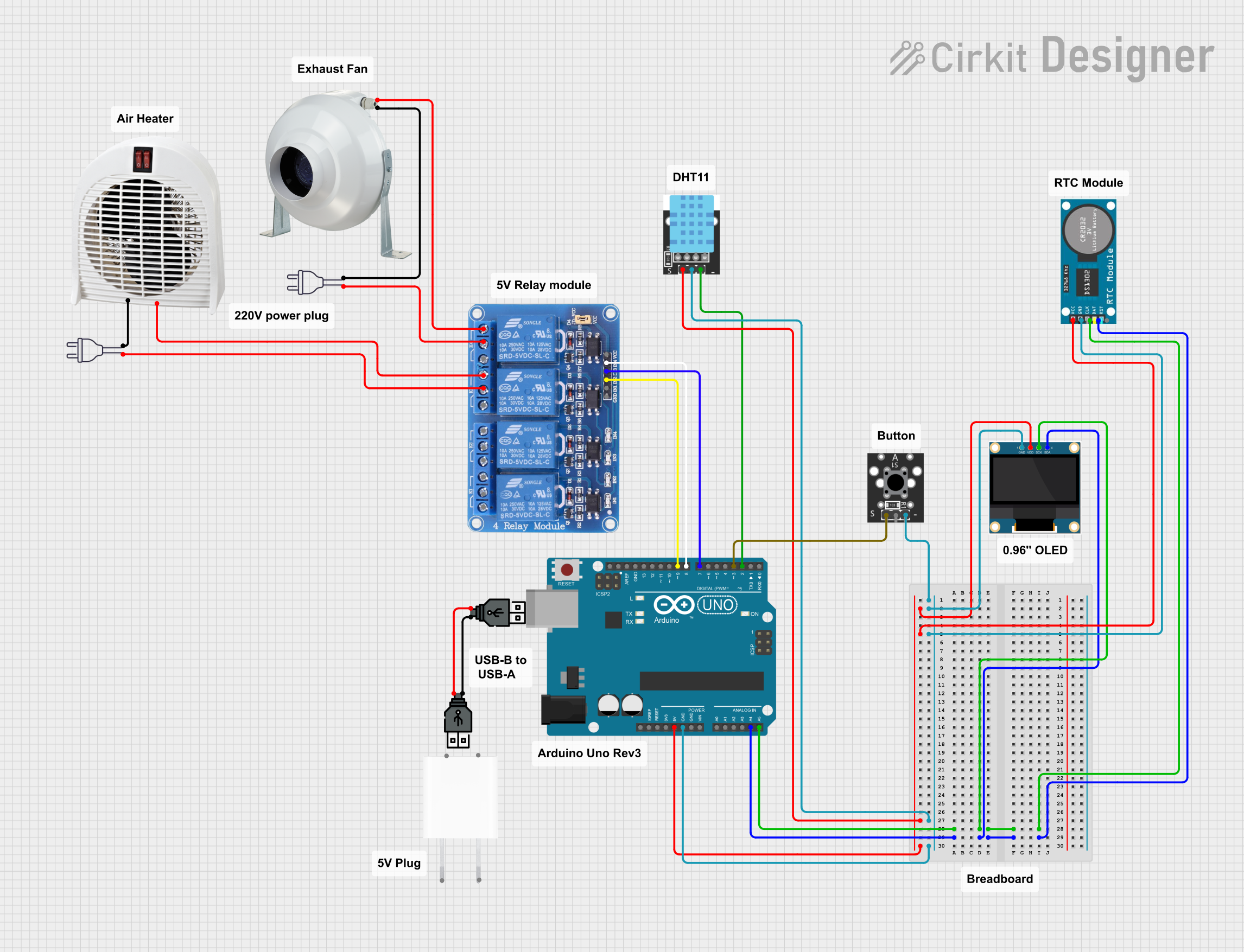
Explore Projects Built with temp
Common Applications and Use Cases
- HVAC systems for temperature monitoring and control
- Weather stations and environmental monitoring
- Industrial automation and process control
- Consumer electronics, such as thermostats and smart home devices
- Data logging and scientific experiments
Technical Specifications
The TEMP sensor is designed to operate efficiently in a variety of environments. Below are its key technical details:
| Parameter | Value |
|---|---|
| Operating Voltage | 3.3V to 5V |
| Output Signal | Analog voltage proportional to temperature |
| Temperature Range | -40°C to +125°C |
| Accuracy | ±0.5°C (typical) |
| Response Time | < 1 second |
| Power Consumption | < 1 mW |
| Package Type | TO-92 or SMD |
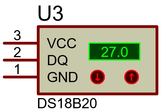
Pin Configuration and Descriptions
The TEMP sensor typically comes with three pins. Below is the pinout description:
| Pin | Name | Description |
|---|---|---|
| 1 | VCC | Power supply input (3.3V to 5V) |
| 2 | OUT | Analog output signal proportional to temperature |
| 3 | GND | Ground connection |
Usage Instructions
How to Use the TEMP Sensor in a Circuit
- Power the Sensor: Connect the VCC pin to a 3.3V or 5V power supply and the GND pin to the ground of your circuit.
- Read the Output: The OUT pin provides an analog voltage that corresponds to the ambient temperature. This can be read using an analog-to-digital converter (ADC) on a microcontroller, such as an Arduino UNO.
- Convert Voltage to Temperature: Use the sensor's datasheet or calibration curve to convert the output voltage into a temperature value.
Important Considerations and Best Practices
- Power Supply Stability: Ensure a stable power supply to avoid fluctuations in the output signal.
- Placement: Place the sensor away from heat sources or direct sunlight to get accurate ambient temperature readings.
- Decoupling Capacitor: Add a small decoupling capacitor (e.g., 0.1 µF) between VCC and GND to filter out noise.
- Calibration: For critical applications, calibrate the sensor using a known temperature reference.
Example: Using TEMP with Arduino UNO
Below is an example of how to connect and read data from the TEMP sensor using an Arduino UNO:
Circuit Connections
- Connect the VCC pin of the TEMP sensor to the 5V pin on the Arduino.
- Connect the GND pin of the TEMP sensor to the GND pin on the Arduino.
- Connect the OUT pin of the TEMP sensor to the A0 analog input pin on the Arduino.
Arduino Code
// TEMP Sensor Example Code
// Reads the analog output from the TEMP sensor and converts it to temperature

const int tempPin = A0; // TEMP sensor output connected to analog pin A0
float voltage;          // Variable to store the sensor's output voltage
float temperature;      // Variable to store the calculated temperature

void setup() {
  Serial.begin(9600); // Initialize serial communication at 9600 baud
}

void loop() {
  int sensorValue = analogRead(tempPin); // Read the analog value from the sensor
  voltage = sensorValue * (5.0 / 1023.0); // Convert ADC value to voltage

  // Convert voltage to temperature (example formula, adjust as per datasheet)
  temperature = (voltage - 0.5) * 100.0; // Assuming 10mV/°C scale and 0.5V offset

  // Print the temperature to the Serial Monitor
  Serial.print("Temperature: ");
  Serial.print(temperature);
  Serial.println(" °C");

  delay(1000); // Wait for 1 second before the next reading
}
Troubleshooting and FAQs
Common Issues and Solutions
No Output Signal
- Cause: Incorrect wiring or loose connections.
- Solution: Double-check the connections and ensure the sensor is powered correctly.
Inaccurate Temperature Readings
- Cause: Sensor placed near heat sources or in direct sunlight.
- Solution: Relocate the sensor to a location with stable ambient conditions.
Fluctuating Output
- Cause: Power supply noise or interference.
- Solution: Add a decoupling capacitor between VCC and GND.
Sensor Not Responding
- Cause: Sensor damaged or operating outside its specified temperature range.
- Solution: Verify the operating conditions and replace the sensor if necessary.
FAQs
Q: Can the TEMP sensor measure surface temperature?
A: No, the TEMP sensor is designed to measure ambient air temperature. For surface temperature measurements, consider using a thermocouple or infrared sensor.
Q: How do I improve the accuracy of the sensor?
A: Use proper calibration techniques and ensure the sensor is placed in a stable environment away from heat sources or airflow.
Q: Can I use the TEMP sensor with a 3.3V microcontroller?
A: Yes, the TEMP sensor operates within a voltage range of 3.3V to 5V, making it compatible with 3.3V systems.
Q: What is the response time of the TEMP sensor?
A: The sensor has a response time of less than 1 second, making it suitable for real-time applications.