How to Use DC/DC booster: Examples, Pinouts, and Specs
Introduction
A DC/DC Booster, also known as a step-up converter, is an electronic component that elevates the level of a direct current (DC) input voltage to a higher DC output voltage. This component is essential in applications where the available power supply voltage is lower than what is required by the system or device. Common applications include battery-powered devices, where boosting the voltage can extend operational life, or in systems that require a stable voltage supply despite varying input conditions.
Explore Projects Built with DC/DC booster
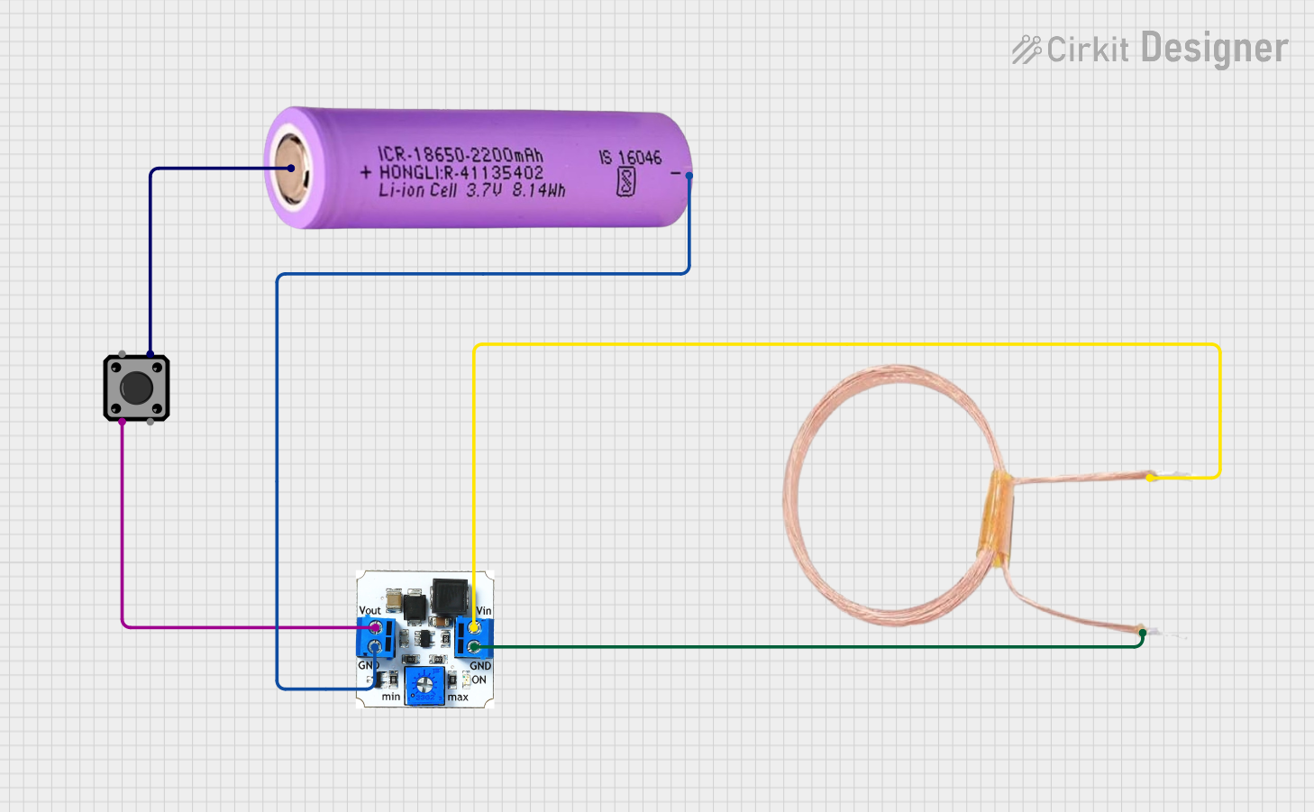
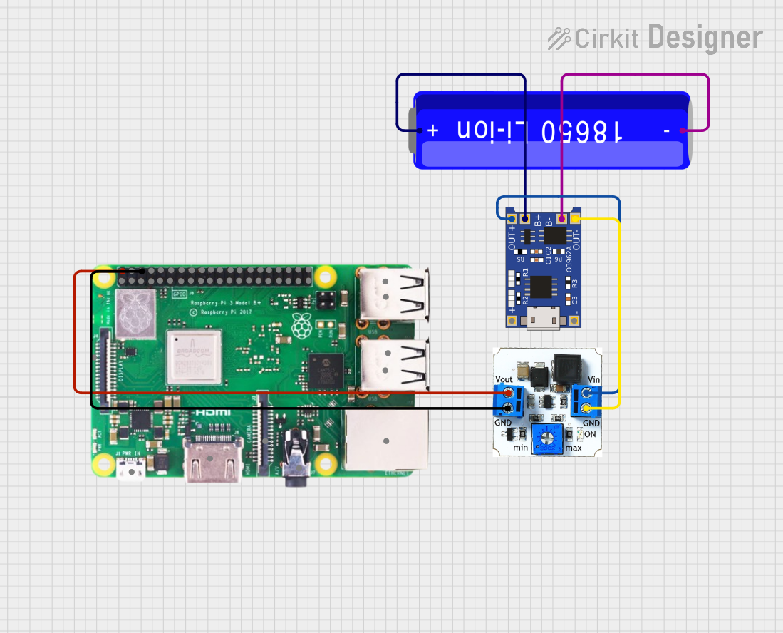


Explore Projects Built with DC/DC booster
Common Applications and Use Cases
- Portable electronics (e.g., powering a 5V device from a 3.7V battery)
- Automotive applications (e.g., converting 12V battery voltage to 24V)
- Renewable energy systems (e.g., solar power converters)
- Powering LEDs or microcontrollers in embedded systems
Technical Specifications
Key Technical Details
- Input Voltage Range: Typically 2.0V to 15V
- Output Voltage Range: Typically 5V to 35V (adjustable via a potentiometer)
- Maximum Output Current: Depends on the model, but often around 2A to 3A
- Efficiency: Up to 90-95% under optimal conditions
- Switching Frequency: Generally in the range of 150kHz to 1.5MHz
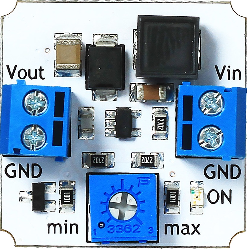
Pin Configuration and Descriptions
| Pin Number | Name | Description |
|---|---|---|
| 1 | VIN | Input voltage to the booster. Connect to the positive terminal of the DC power source. |
| 2 | GND | Ground pin. Connect to the negative terminal of the DC power source. |
| 3 | VOUT | Output voltage from the booster. Connect to the positive terminal of the load. |
| 4 | GND | Ground pin for the output. Connect to the negative terminal of the load. |
Usage Instructions
How to Use the Component in a Circuit
- Connection: Connect the input voltage and ground to the respective VIN and GND pins. Ensure that the input voltage is within the specified range for the booster module.
- Adjustment: Use the onboard potentiometer to adjust the output voltage to the desired level. Measure the output voltage with a multimeter while adjusting.
- Load Connection: Connect the load to the VOUT and GND pins, ensuring that the load does not exceed the maximum output current rating of the booster.
- Power On: Once everything is connected and adjusted, power on the input supply to start using the boosted voltage.
Important Considerations and Best Practices
- Heat Dissipation: DC/DC boosters can generate heat during operation. Ensure adequate ventilation or add a heatsink if necessary.
- Input Voltage: Never exceed the maximum input voltage rating as it can damage the booster.
- Output Current: Do not draw more current than the maximum rating to prevent overheating and potential failure.
- Voltage Adjustment: Make fine adjustments to the potentiometer to avoid sudden increases in output voltage that could damage sensitive components.
Troubleshooting and FAQs
Common Issues Users Might Face
- Insufficient Output Voltage: Ensure the input voltage is adequate and the potentiometer is correctly adjusted.
- Overheating: Check if the current draw is within the module's limits and improve heat dissipation.
- No Output: Verify connections, input voltage, and that the module is not damaged.
Solutions and Tips for Troubleshooting
- If the output voltage is not stable or is lower than expected, check the input voltage under load conditions and ensure it does not drop below the minimum required.
- In case of overheating, reduce the load current, improve ventilation, or add a heatsink to the module.
- If there is no output, recheck all connections, ensure the input voltage is present and within range, and inspect the module for any visible damage.
FAQs
Q: Can I use a DC/DC booster to charge batteries? A: Yes, but you must ensure that the output voltage and current are appropriate for the battery being charged.
Q: What is the maximum input voltage I can apply to the booster? A: This depends on the specific model of the booster. Refer to the technical specifications for the maximum input voltage.
Q: How do I know if the booster is working efficiently? A: Measure the input and output power (voltage and current) and calculate the efficiency as (Output Power/Input Power) x 100%.
Q: Can I use multiple boosters in parallel to increase the output current? A: It is not recommended to use boosters in parallel due to potential issues with load sharing and synchronization.
Example Code for Arduino UNO
Below is an example code snippet for reading the output voltage of a DC/DC booster using an Arduino UNO. This assumes the use of an analog input to measure the voltage.
const int analogPin = A0; // Analog pin connected to the output of the booster
const float referenceVoltage = 5.0; // Reference voltage of Arduino UNO
const int resolution = 1024; // Resolution of the analog-to-digital converter
const float voltageDividerRatio = 2.0; // Ratio of the voltage divider (if used)

void setup() {
  Serial.begin(9600);
}

void loop() {
  int sensorValue = analogRead(analogPin); // Read the analog input value
  float voltage = (sensorValue * referenceVoltage / resolution) * voltageDividerRatio;
  Serial.print("Booster Output Voltage: ");
  Serial.print(voltage);
  Serial.println(" V");
  delay(1000); // Wait for a second before reading again
}
Note: If the output voltage of the booster is higher than the reference voltage of the Arduino, a voltage divider must be used to bring the voltage within the readable range for the Arduino's analog input. Adjust the voltageDividerRatio accordingly.