How to Use MAX30105: Examples, Pinouts, and Specs
Introduction
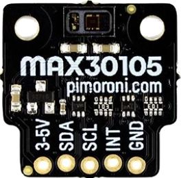
The MAX30105, manufactured by Pimoroni (Part ID: PIM438), is a highly versatile optical sensor designed for heart rate and SpO2 (blood oxygen saturation) monitoring. It integrates a photodetector, LED drivers, and ambient light rejection circuitry, making it ideal for wearable health devices and other optical sensing applications. Additionally, the MAX30105 can be used for particle detection in applications such as smoke detection and environmental monitoring.
Explore Projects Built with MAX30105


Explore Projects Built with MAX30105
Common Applications
- Wearable health devices (e.g., fitness trackers, smartwatches)
- Heart rate and SpO2 monitoring
- Smoke detection and particle sensing
- Environmental monitoring
- Proximity sensing
Technical Specifications
The MAX30105 is a compact and powerful sensor with the following key specifications:
| Parameter | Value |
|---|---|
| Operating Voltage | 1.8V (logic) and 3.3V (LEDs) |
| Current Consumption | 600 µA (typical, during operation) |
| LED Wavelengths | Red: 660 nm, Infrared: 880 nm, Green: 537 nm |
| Communication Interface | I2C (7-bit address: 0x57) |
| Operating Temperature Range | -40°C to +85°C |
| Dimensions | 5.6 mm x 3.3 mm x 1.55 mm |
Pin Configuration and Descriptions
The MAX30105 module typically comes with the following pinout:
| Pin Name | Description |
|---|---|
| VIN | Power supply input (3.3V or 5V, depending on the breakout board configuration). |
| GND | Ground connection. |
| SDA | I2C data line for communication. |
| SCL | I2C clock line for communication. |
| INT | Interrupt pin (active low, optional for event-driven applications). |
Usage Instructions
How to Use the MAX30105 in a Circuit
- Power Supply: Connect the VIN pin to a 3.3V or 5V power source (depending on the breakout board). Connect the GND pin to the ground of your circuit.
- I2C Communication: Connect the SDA and SCL pins to the corresponding I2C pins on your microcontroller. Use pull-up resistors (typically 4.7 kΩ) on the SDA and SCL lines if not already included on the breakout board.
- Interrupt Pin (Optional): If you want to use the interrupt feature, connect the INT pin to a GPIO pin on your microcontroller and configure it as an input.
Important Considerations and Best Practices
- Ambient Light Interference: Ensure the sensor is shielded from direct ambient light to avoid interference with measurements.
- Placement: For heart rate and SpO2 monitoring, place the sensor in contact with the skin (e.g., fingertip or wrist) for accurate readings.
- I2C Address: The default I2C address of the MAX30105 is
0x57. Ensure no other devices on the I2C bus share this address. - Power Consumption: To save power, use the shutdown mode when the sensor is not in use.
Example Code for Arduino UNO
Below is an example of how to interface the MAX30105 with an Arduino UNO to read basic data:
#include <Wire.h>
#include "SparkFun_MAX30105.h" // Include the MAX30105 library

MAX30105 particleSensor; // Create an instance of the MAX30105 class

void setup() {
  Serial.begin(9600); // Initialize serial communication
  Serial.println("Initializing MAX30105...");

  // Initialize the sensor
  if (!particleSensor.begin()) {
    Serial.println("MAX30105 was not found. Please check wiring/power.");
    while (1); // Halt the program if the sensor is not detected
  }

  // Configure the sensor for heart rate and SpO2 monitoring
  particleSensor.setup(); // Use default settings
  particleSensor.setPulseAmplitudeRed(0x0A); // Set red LED to low power
  particleSensor.setPulseAmplitudeIR(0x0A);  // Set IR LED to low power
}

void loop() {
  // Read and print the IR value
  long irValue = particleSensor.getIR(); // Get the IR data
  Serial.print("IR Value: ");
  Serial.println(irValue);

  delay(100); // Wait 100ms before the next reading
}
Notes on the Code
- The
SparkFun_MAX30105.hlibrary is required for this example. Install it via the Arduino Library Manager. - Adjust the LED power levels (
setPulseAmplitudeRedandsetPulseAmplitudeIR) based on your application requirements.
Troubleshooting and FAQs
Common Issues and Solutions
Sensor Not Detected
- Cause: Incorrect wiring or I2C address conflict.
- Solution: Double-check the connections and ensure the I2C address matches the default (
0x57).
Inaccurate Readings
- Cause: Ambient light interference or improper placement.
- Solution: Shield the sensor from ambient light and ensure proper contact with the skin.
High Power Consumption
- Cause: LEDs running at full power unnecessarily.
- Solution: Reduce LED power levels using the
setPulseAmplitudefunctions.
Interrupt Pin Not Working
- Cause: Interrupt pin not configured correctly.
- Solution: Verify the interrupt pin is connected to a GPIO pin and configured as an input.
FAQs
Q: Can the MAX30105 be used for smoke detection?
A: Yes, the MAX30105 can detect particles in the air, making it suitable for smoke detection applications.
Q: What is the maximum I2C speed supported?
A: The MAX30105 supports I2C speeds up to 400 kHz (Fast Mode).
Q: Can I use the MAX30105 with a 5V microcontroller?
A: Yes, but ensure the breakout board includes level-shifting circuitry for I2C communication.
Q: How do I improve SpO2 accuracy?
A: Ensure the sensor is in direct contact with the skin and minimize motion during measurements.