How to Use Terminal PCB 3 Pin: Examples, Pinouts, and Specs
Introduction
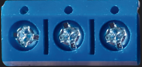
The Terminal PCB 3 Pin is a compact and reliable 3-pin terminal block designed for printed circuit boards (PCBs). It provides a convenient way to connect and disconnect wires in electronic circuits without the need for soldering. This component is widely used in applications where secure and removable wire connections are required, such as power distribution, signal connections, and prototyping.
Explore Projects Built with Terminal PCB 3 Pin


Explore Projects Built with Terminal PCB 3 Pin
Common Applications and Use Cases
- Power supply connections in electronic devices
- Signal wiring in control systems
- Prototyping and testing circuits
- Industrial automation and robotics
- Audio and communication systems
Technical Specifications
The following table outlines the key technical details of the Terminal PCB 3 Pin:
| Parameter | Specification |
|---|---|
| Number of Pins | 3 |
| Rated Voltage | 300V AC/DC |
| Rated Current | 10A |
| Wire Gauge Support | 26-12 AWG |
| Pitch (Pin Spacing) | 5.08 mm (0.2 inches) |
| Material (Housing) | Flame-retardant thermoplastic (UL94-V0) |
| Contact Material | Copper alloy with tin plating |
| Operating Temperature | -40°C to +105°C |
| Mounting Type | Through-hole |
Pin Configuration and Descriptions
The Terminal PCB 3 Pin has three pins, each corresponding to a terminal for wire connections. The pin configuration is as follows:
| Pin Number | Description |
|---|---|
| 1 | Terminal 1 (Input/Output) |
| 2 | Terminal 2 (Input/Output) |
| 3 | Terminal 3 (Input/Output) |
Usage Instructions
How to Use the Terminal PCB 3 Pin in a Circuit
Mounting the Terminal Block:
- Insert the pins of the terminal block into the corresponding through-hole pads on the PCB.
- Solder the pins securely to the PCB to ensure a stable connection.
Connecting Wires:
- Strip the insulation from the wire ends (approximately 5-7 mm).
- Insert the stripped wire ends into the terminal openings.
- Tighten the screws on the terminal block to secure the wires in place.
Testing the Connection:
- Verify the connections using a multimeter to ensure proper continuity.
- Power on the circuit and check for stable operation.
Important Considerations and Best Practices
- Ensure the wire gauge is within the supported range (26-12 AWG) to avoid loose or improper connections.
- Do not overtighten the screws, as this may damage the wires or the terminal block.
- Use a PCB layout that matches the pin pitch (5.08 mm) to ensure proper alignment.
- Avoid exposing the terminal block to excessive heat during soldering to prevent damage to the housing.
Example: Connecting to an Arduino UNO
The Terminal PCB 3 Pin can be used to connect external components, such as sensors or power supplies, to an Arduino UNO. Below is an example of how to use it to connect a 12V power supply to an Arduino project:
Circuit Diagram
- Connect the positive terminal of the power supply to Pin 1 of the terminal block.
- Connect the negative terminal of the power supply to Pin 2 of the terminal block.
- Use Pin 3 for an additional connection, such as a ground wire for another component.
Sample Code
// Example code for using a 12V power supply with an Arduino UNO
// Ensure proper connections via the Terminal PCB 3 Pin

void setup() {
  // Initialize serial communication for debugging
  Serial.begin(9600);

  // Example: Set pin 13 as an output to control an LED
  pinMode(13, OUTPUT);
}

void loop() {
  // Blink the LED connected to pin 13
  digitalWrite(13, HIGH); // Turn the LED on
  delay(1000);            // Wait for 1 second
  digitalWrite(13, LOW);  // Turn the LED off
  delay(1000);            // Wait for 1 second
}
Troubleshooting and FAQs
Common Issues and Solutions
Loose Wire Connections:
- Issue: Wires are not securely held in the terminal block.
- Solution: Ensure the screws are tightened properly and the wire gauge is within the supported range.
Intermittent Connections:
- Issue: The circuit works intermittently or fails under load.
- Solution: Check for cold solder joints on the PCB and re-solder if necessary. Verify the wire connections.
Overheating:
- Issue: The terminal block becomes hot during operation.
- Solution: Ensure the current does not exceed the rated 10A. Use thicker wires if necessary.
Misalignment on PCB:
- Issue: The terminal block does not fit properly on the PCB.
- Solution: Verify the PCB layout matches the pin pitch (5.08 mm).
FAQs
Q1: Can I use the Terminal PCB 3 Pin for high-frequency signals?
A1: While it is primarily designed for power and low-frequency signals, it can handle high-frequency signals if proper shielding and grounding are implemented.
Q2: Is the Terminal PCB 3 Pin suitable for outdoor use?
A2: The terminal block is not waterproof. For outdoor use, ensure it is housed in a weatherproof enclosure.
Q3: Can I use it with stranded wires?
A3: Yes, stranded wires are supported. Ensure the strands are twisted tightly before insertion to improve connection stability.
Q4: What tools are required for installation?
A4: You will need a screwdriver for tightening the screws and a soldering iron for mounting the terminal block to the PCB.