How to Use Terminal Block BLUE: Examples, Pinouts, and Specs
Introduction
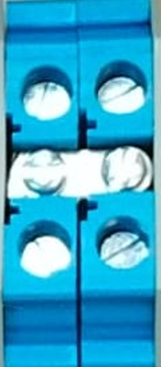
A terminal block is a modular, insulated block designed to secure two or more wires together, ensuring a reliable and safe electrical connection. The blue terminal block is commonly used in electrical systems to denote neutral or ground connections, providing a clear visual indicator for wiring organization. Its modular design allows for easy installation, maintenance, and troubleshooting in a variety of applications.
Explore Projects Built with Terminal Block BLUE


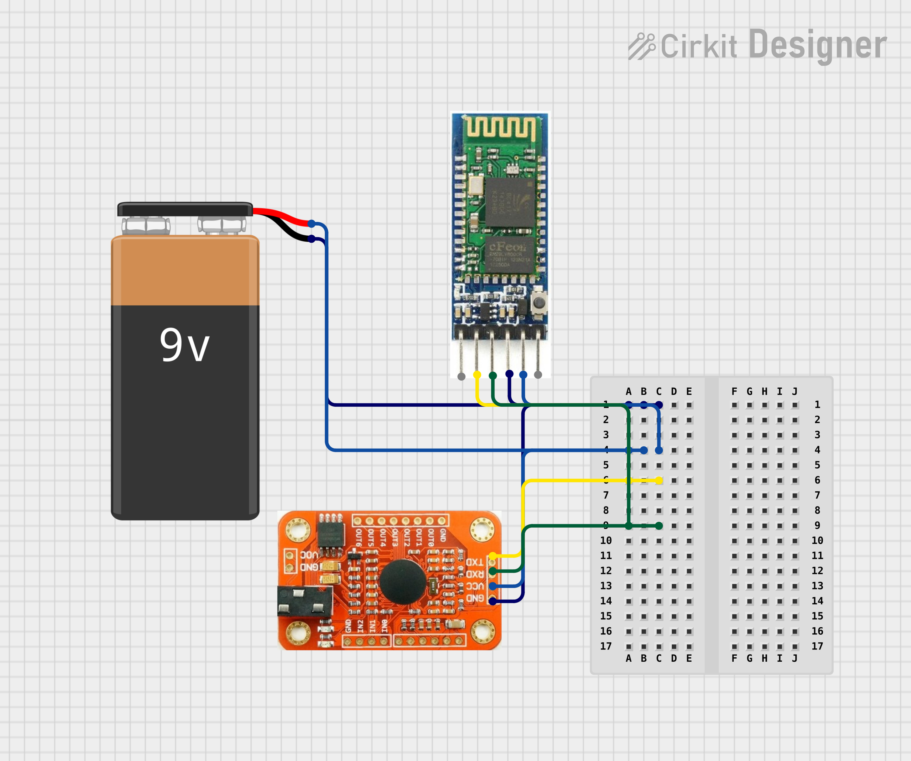
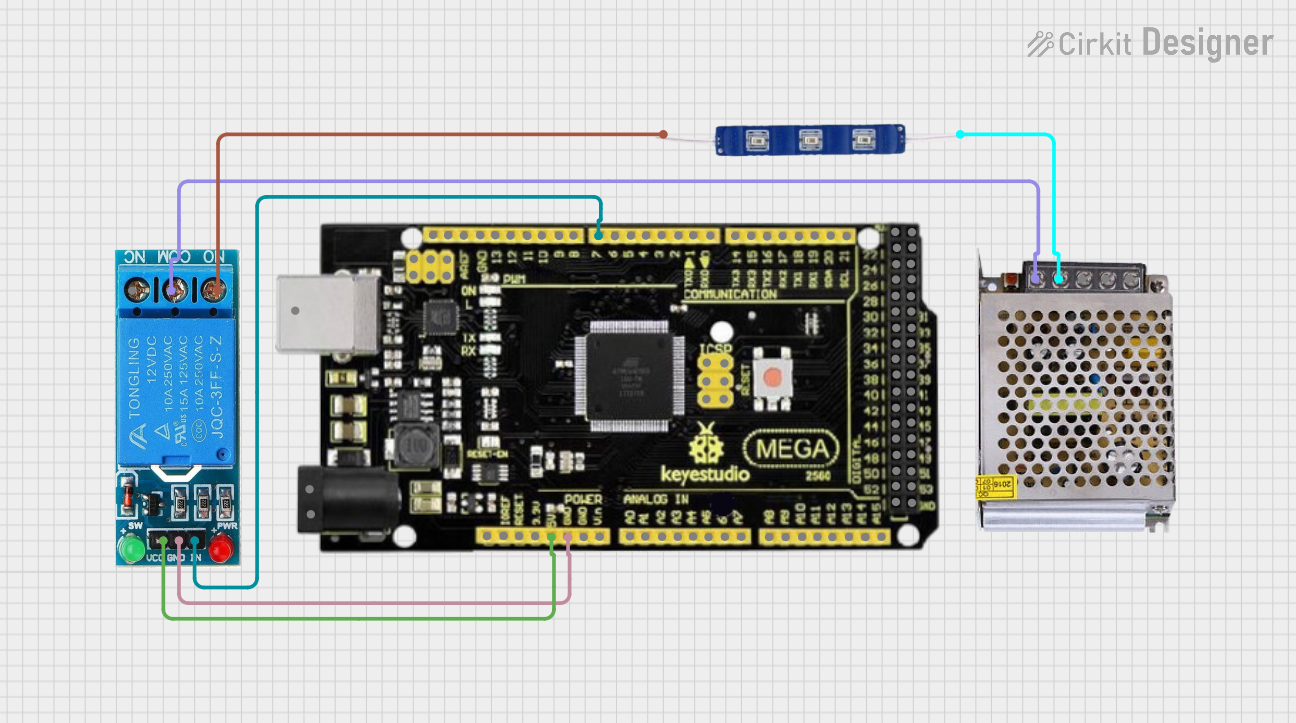
Explore Projects Built with Terminal Block BLUE
Common Applications and Use Cases
- Electrical distribution panels for neutral or ground connections
- Industrial control systems and automation equipment
- Power supplies and circuit protection systems
- Home and commercial electrical wiring
- Prototyping and testing circuits
Technical Specifications
Key Technical Details
- Material: Flame-retardant plastic housing (typically polyamide or similar)
- Rated Voltage: Up to 600V (varies by model)
- Rated Current: Typically 10A to 30A (check specific model for exact rating)
- Wire Size Compatibility: 22 AWG to 10 AWG (varies by model)
- Mounting Type: Screw-type or DIN rail mount
- Operating Temperature: -40°C to +105°C
- Color: Blue (commonly used for neutral or ground connections)
Pin Configuration and Descriptions
Terminal blocks do not have traditional "pins" like ICs or connectors. Instead, they feature screw terminals or spring clamps for wire connections. Below is a general description of the terminal block's structure:
| Terminal Block Part | Description |
|---|---|
| Screw Terminal | Secures the wire in place by tightening a screw. |
| Wire Entry Point | The opening where the wire is inserted. |
| Insulated Housing | Provides electrical insulation and mechanical protection. |
| Mounting Slot | Allows the terminal block to be mounted on a DIN rail or panel. |
| Labeling Area | Space for marking or labeling the connection for easy identification. |
Usage Instructions
How to Use the Terminal Block in a Circuit
Prepare the Wires:
- Strip the insulation from the wire ends (typically 5-10mm, depending on the terminal block size).
- Ensure the wire ends are clean and free of frayed strands.
Insert the Wires:
- Loosen the screw terminal using a screwdriver.
- Insert the stripped wire end into the wire entry point.
- Tighten the screw terminal to secure the wire. Ensure the connection is firm but avoid overtightening, which could damage the wire or terminal.
Mount the Terminal Block:
- If using a DIN rail mount, snap the terminal block onto the rail.
- For panel-mounted blocks, secure them using screws or other mounting hardware.
Label the Connections:
- Use the labeling area to mark the purpose of each connection (e.g., "Neutral" or "Ground").
Important Considerations and Best Practices
- Always ensure the terminal block's voltage and current ratings match the requirements of your circuit.
- Use appropriate wire sizes as specified by the terminal block's specifications.
- Avoid overtightening screws, as this can damage the wire or the terminal block.
- For high-vibration environments, consider using spring-clamp terminal blocks for a more secure connection.
- Regularly inspect connections for signs of wear, corrosion, or loosening.
Example: Connecting a Terminal Block to an Arduino UNO
While terminal blocks are not directly connected to an Arduino UNO, they can be used to organize and distribute power or signals in circuits involving the Arduino. Below is an example of how to use a terminal block to distribute 5V power from an Arduino:
// Example: Distributing 5V power from Arduino to multiple components
// Terminal block is used to organize and distribute the 5V and GND lines

// No specific code is required for the terminal block itself, but ensure
// proper wiring as follows:
// - Connect Arduino 5V pin to one terminal of the block (e.g., Terminal 1).
// - Connect Arduino GND pin to another terminal (e.g., Terminal 2).
// - Use the remaining terminals to distribute 5V and GND to other components.

// Example wiring:
// Terminal 1: Arduino 5V -> Component 1, Component 2, etc.
// Terminal 2: Arduino GND -> Component 1, Component 2, etc.
Troubleshooting and FAQs
Common Issues and Solutions
| Issue | Solution |
|---|---|
| Loose wire connections | Ensure the screw terminals are tightened securely without overtightening. |
| Wire slipping out of the terminal | Check that the wire is stripped to the correct length and fully inserted. |
| Overheating of the terminal block | Verify that the current does not exceed the terminal block's rated capacity. |
| Corrosion or oxidation of connections | Use terminal blocks with anti-corrosion coatings or clean the connections. |
| Difficulty mounting the terminal block | Ensure the correct mounting hardware or DIN rail is used. |
FAQs
Can I use a blue terminal block for live or hot connections?
- While it is technically possible, blue terminal blocks are typically reserved for neutral or ground connections to maintain standard wiring practices.
What tools are needed to use a terminal block?
- A screwdriver (flathead or Phillips, depending on the terminal block design) and wire strippers are usually sufficient.
Can terminal blocks handle high-frequency signals?
- Terminal blocks are primarily designed for power distribution and low-frequency signals. For high-frequency applications, consider specialized connectors.
How do I ensure a secure connection in high-vibration environments?
- Use spring-clamp terminal blocks instead of screw-type blocks, as they provide better resistance to vibration.
By following this documentation, you can effectively use the blue terminal block in your electrical and electronic projects, ensuring safe and reliable connections.