How to Use MAX98375: Examples, Pinouts, and Specs
Introduction
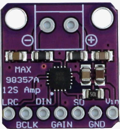
The MAX98375 is a high-efficiency Class D audio amplifier designed to deliver a high-quality audio experience with a 3.2W output power. This component is particularly suitable for portable and battery-powered applications due to its low quiescent current draw. Common applications include wireless speakers, mobile phones, laptops, and other portable audio devices where space and power efficiency are critical.
Explore Projects Built with MAX98375


Explore Projects Built with MAX98375
Technical Specifications
Key Technical Details
- Output Power: 3.2W (at 4Ω load and 5V supply)
- Supply Voltage Range: 2.5V to 5.5V
- Quiescent Current: Typically 2mA
- Efficiency: Up to 92%
- THD+N: 0.015% (Total Harmonic Distortion + Noise)
- Signal-to-Noise Ratio (SNR): 103dB
- Load Impedance: Compatible with 4Ω to 8Ω speakers
- Audio Input: Supports I2S, left-justified, right-justified, TDM, and PDM data
- Amplifier Type: Class D
Pin Configuration and Descriptions
| Pin Number | Pin Name | Description |
|---|---|---|
| 1 | PVDD | Power supply for the output stage. |
| 2 | GND | Ground reference for the amplifier. |
| 3 | IN+ | Positive audio input. |
| 4 | IN- | Negative audio input. |
| 5 | GAIN | Gain selection input. |
| 6 | SD | Shutdown control input (active low). |
| 7 | BCLK | Bit clock input for digital audio data. |
| 8 | LRC | Left/Right clock input for digital audio data. |
| 9 | DIN | Digital audio data input. |
| 10 | BST | Bypass pin for the internal boost converter. |
Usage Instructions
Integrating the MAX98375 into a Circuit
Power Supply: Connect a clean power supply to the PVDD pin (1) and ground to the GND pin (2). Ensure the voltage is within the specified range (2.5V to 5.5V).
Audio Input: For analog input, connect the audio source to IN+ (3) and IN- (4). For digital audio, use BCLK (7), LRC (8), and DIN (9) to interface with the audio source.
Gain Setting: The GAIN pin (5) can be used to set the amplifier gain. Refer to the datasheet for the appropriate resistor values to achieve the desired gain.
Shutdown Control: The SD pin (6) can be used to put the amplifier into a low-power shutdown mode when driven low.
Speaker Connection: Connect the speaker between the OUT+ and OUT- pins, ensuring the speaker's impedance is within the supported range.
Best Practices
- Use decoupling capacitors close to the power supply pins to minimize noise.
- Keep audio input lines as short as possible to reduce susceptibility to EMI.
- Ensure proper heat sinking if operating at high output power levels to prevent thermal shutdown.
Troubleshooting and FAQs
Common Issues
- No Sound Output: Check power supply connections, ensure the SD pin is not pulled low, and verify that the audio input is correctly connected and within the accepted format and levels.
- Distorted Sound: Ensure the speaker impedance is within the specified range and check for proper gain settings. Also, verify that the power supply is stable and not causing clipping.
Solutions and Tips
- Low Volume: Adjust the gain setting or check if the input signal level is too low.
- Overheating: Provide adequate ventilation and consider adding a heatsink to the MAX98375.
FAQs
Q: Can the MAX98375 be used with a mono speaker? A: Yes, the MAX98375 can be configured for mono output.
Q: What is the recommended power supply filtering? A: A low-ESR ceramic capacitor (typically 1µF) should be placed as close as possible to the PVDD and GND pins.
Q: How do I put the MAX98375 into shutdown mode? A: Pull the SD pin low to enter shutdown mode. When the pin is left floating or driven high, the amplifier is active.
Example Code for Arduino UNO
Below is an example of how to use the MAX98375 with an Arduino UNO for I2S audio output.
#include <Arduino.h>
#include <Wire.h>
#include <I2S.h>

// Define the I2S pins for the Arduino UNO
#define I2S_BCLK 13
#define I2S_LRC 10
#define I2S_DIN 11
#define I2S_SD 9 // Shutdown pin for the MAX98375

void setup() {
  // Initialize I2S with the desired audio settings
  I2S.begin(I2S_PHILIPS_MODE, 44100, 16);

  // Set the shutdown pin to output and turn off the amplifier
  pinMode(I2S_SD, OUTPUT);
  digitalWrite(I2S_SD, LOW);
}

void loop() {
  // Example: Generate a 1kHz sine wave (not a complete implementation)
  int sample;
  for (int i = 0; i < 44100; i++) {
    sample = 32767 * sin(2 * PI * 1000 * i / 44100);
    I2S.write(sample);
  }

  // To turn on the amplifier, set the shutdown pin high
  digitalWrite(I2S_SD, HIGH);

  // Your audio processing code goes here

  // To turn off the amplifier, set the shutdown pin low
  digitalWrite(I2S_SD, LOW);
}
Note: This code is for illustrative purposes and may require additional setup and configuration depending on the specific application and audio source. Always refer to the MAX98375 datasheet and the Arduino I2S library documentation for detailed information and advanced usage.