How to Use DESPI-C02: Examples, Pinouts, and Specs
Introduction
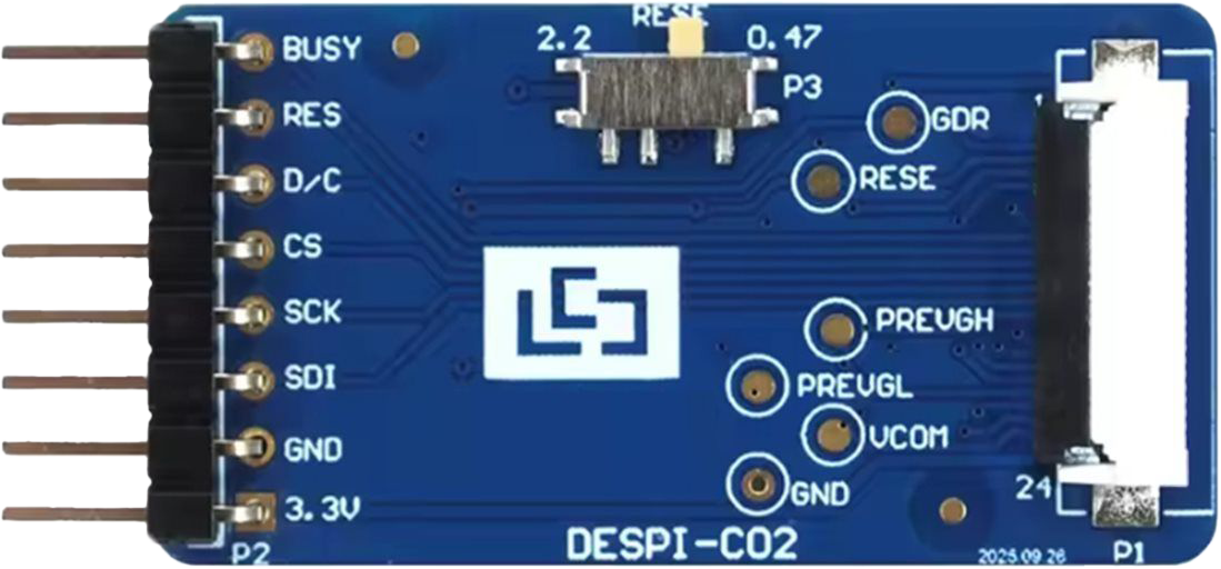
The DESPI-C02 is a digital signal processing interface designed for efficient data handling and communication in electronic systems. It is commonly used in applications requiring high-speed data transfer and processing, such as telecommunications, audio processing, and real-time data acquisition systems. Its robust design and versatile functionality make it a popular choice for engineers working on performance-critical projects.
Explore Projects Built with DESPI-C02
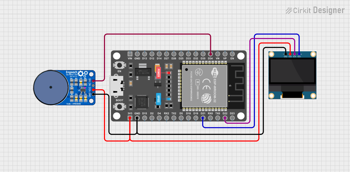
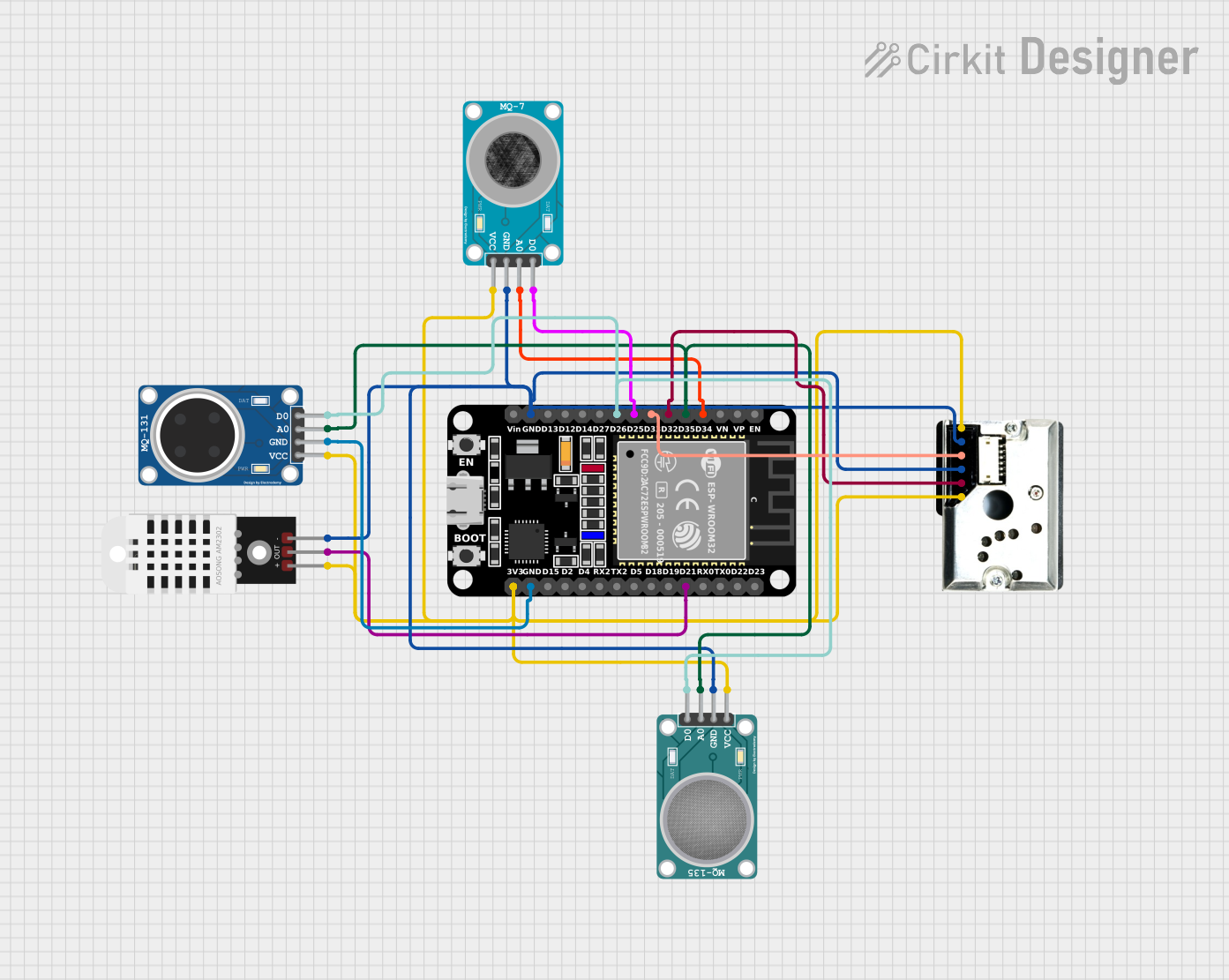
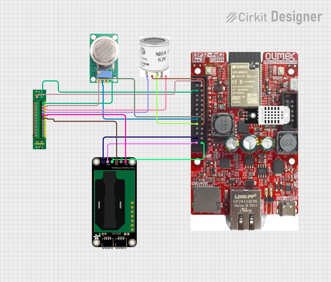
Explore Projects Built with DESPI-C02
Common Applications:
- High-speed data communication systems
- Audio and video signal processing
- Real-time data acquisition and analysis
- Embedded systems requiring efficient data handling
Technical Specifications
The DESPI-C02 is engineered to deliver reliable performance in demanding environments. Below are its key technical specifications:
General Specifications:
| Parameter | Value |
|---|---|
| Operating Voltage | 3.3V to 5V |
| Maximum Data Rate | 100 Mbps |
| Power Consumption | 250 mW (typical) |
| Operating Temperature | -40°C to +85°C |
| Communication Protocol | SPI (Serial Peripheral Interface) |
| Package Type | 16-pin TSSOP |
Pin Configuration:
The DESPI-C02 features a 16-pin configuration. The table below describes each pin:
| Pin Number | Pin Name | Description |
|---|---|---|
| 1 | VCC | Power supply input (3.3V to 5V) |
| 2 | GND | Ground connection |
| 3 | MISO | Master In Slave Out - SPI data output |
| 4 | MOSI | Master Out Slave In - SPI data input |
| 5 | SCK | SPI Clock input |
| 6 | CS | Chip Select - Active low |
| 7 | RESET | Reset input - Active low |
| 8 | INT | Interrupt output |
| 9 | DATA0 | General-purpose data line 0 |
| 10 | DATA1 | General-purpose data line 1 |
| 11 | DATA2 | General-purpose data line 2 |
| 12 | DATA3 | General-purpose data line 3 |
| 13 | NC | Not connected |
| 14 | NC | Not connected |
| 15 | TEST | Test mode input (leave unconnected for normal use) |
| 16 | CLKOUT | Clock output for synchronization |
Usage Instructions
The DESPI-C02 is straightforward to integrate into a circuit. Below are the steps and best practices for using this component effectively:
Steps to Use:
- Power Supply: Connect the VCC pin to a stable 3.3V or 5V power source and the GND pin to the ground.
- SPI Communication: Connect the SPI pins (MISO, MOSI, SCK, and CS) to the corresponding pins on your microcontroller or processor.
- Reset: Use the RESET pin to initialize the component. Pull it low momentarily to reset the device.
- Interrupt Handling: If required, connect the INT pin to your microcontroller to handle interrupts.
- Data Lines: Use the DATA0 to DATA3 pins for additional data handling or custom configurations.
Best Practices:
- Use decoupling capacitors (e.g., 0.1 µF) near the VCC pin to ensure stable operation.
- Keep SPI traces short and use proper grounding to minimize noise.
- Avoid leaving unused pins floating; connect them to GND or VCC as specified in the datasheet.
- Ensure the SPI clock frequency does not exceed the maximum supported data rate of 100 Mbps.
Example: Connecting DESPI-C02 to Arduino UNO
Below is an example of how to connect and use the DESPI-C02 with an Arduino UNO:
Circuit Connections:
| DESPI-C02 Pin | Arduino UNO Pin |
|---|---|
| VCC | 5V |
| GND | GND |
| MISO | Pin 12 |
| MOSI | Pin 11 |
| SCK | Pin 13 |
| CS | Pin 10 |
| RESET | Pin 9 |
Arduino Code Example:
#include <SPI.h>

// Define pin connections
const int chipSelectPin = 10; // Chip Select pin
const int resetPin = 9;       // Reset pin

void setup() {
  // Initialize SPI communication
  SPI.begin();

  // Configure pins
  pinMode(chipSelectPin, OUTPUT);
  pinMode(resetPin, OUTPUT);

  // Reset the DESPI-C02
  digitalWrite(resetPin, LOW);  // Pull reset pin low
  delay(10);                    // Wait for 10ms
  digitalWrite(resetPin, HIGH); // Release reset pin

  // Initialize the DESPI-C02
  digitalWrite(chipSelectPin, HIGH); // Deselect the chip
  Serial.begin(9600);                // Start serial communication
}

void loop() {
  // Example: Send data to DESPI-C02
  digitalWrite(chipSelectPin, LOW);  // Select the chip
  SPI.transfer(0x55);               // Send a byte (example: 0x55)
  digitalWrite(chipSelectPin, HIGH); // Deselect the chip

  delay(1000); // Wait for 1 second
}
Troubleshooting and FAQs
Common Issues:
No Response from DESPI-C02:
- Cause: Incorrect SPI connections or configuration.
- Solution: Double-check the SPI pin connections and ensure the SPI clock frequency is within the supported range.
Device Not Resetting:
- Cause: RESET pin not properly pulled low.
- Solution: Ensure the RESET pin is momentarily pulled low during initialization.
Data Corruption:
- Cause: Noise or interference on SPI lines.
- Solution: Use shorter traces, proper grounding, and decoupling capacitors.
Interrupts Not Triggering:
- Cause: INT pin not connected or configured.
- Solution: Verify the INT pin connection and configure the microcontroller to handle interrupts.
FAQs:
Q: Can the DESPI-C02 operate at 3.3V?
- A: Yes, the DESPI-C02 supports both 3.3V and 5V operation.
Q: What is the maximum SPI clock frequency?
- A: The maximum supported SPI clock frequency is 100 Mbps.
Q: Are the DATA pins mandatory for operation?
- A: No, the DATA pins are optional and can be used for additional data handling or custom configurations.
Q: Can I leave the TEST pin unconnected?
- A: Yes, the TEST pin should be left unconnected for normal operation.
By following this documentation, you can effectively integrate and utilize the DESPI-C02 in your projects.