How to Use L298N Motor Driver: Examples, Pinouts, and Specs
Introduction
The L298N Motor Driver, manufactured by QWER (Part ID: L298N), is an integrated circuit designed to control two DC motors or a single stepper motor. It supports bidirectional control and speed regulation using PWM (Pulse Width Modulation). With a current handling capacity of up to 2A per channel and an operating voltage range of 5V to 35V, the L298N is a versatile and reliable choice for robotics, automation, and motor control applications.
Explore Projects Built with L298N Motor Driver

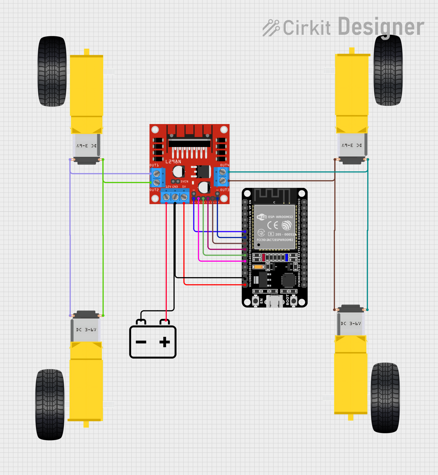

Explore Projects Built with L298N Motor Driver
Common Applications
- Robotics: Driving wheels or robotic arms
- Automation systems: Conveyor belts, actuators
- DIY projects: RC cars, drones, and other motorized devices
- Stepper motor control for CNC machines or 3D printers
Technical Specifications
Below are the key technical details of the L298N Motor Driver:
| Parameter | Value |
|---|---|
| Manufacturer | QWER |
| Part ID | L298N |
| Operating Voltage | 5V to 35V |
| Maximum Current | 2A per channel |
| Logic Voltage | 5V |
| PWM Frequency | Up to 20 kHz |
| Number of Channels | 2 (H-Bridge configuration) |
| Motor Types Supported | DC motors, stepper motors |
| Operating Temperature | -25°C to +130°C |
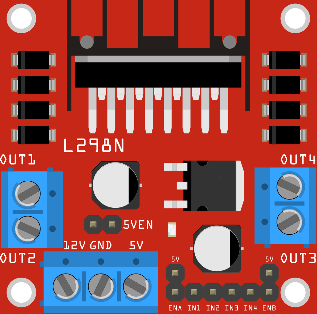
Pin Configuration and Descriptions
The L298N Motor Driver has the following pin configuration:
| Pin Name | Pin Type | Description |
|---|---|---|
| IN1 | Input | Control input for Motor A (logic HIGH or LOW) |
| IN2 | Input | Control input for Motor A (logic HIGH or LOW) |
| IN3 | Input | Control input for Motor B (logic HIGH or LOW) |
| IN4 | Input | Control input for Motor B (logic HIGH or LOW) |
| ENA | Input (PWM) | Enable pin for Motor A (connect to PWM for speed control) |
| ENB | Input (PWM) | Enable pin for Motor B (connect to PWM for speed control) |
| OUT1 | Output | Output to Motor A terminal 1 |
| OUT2 | Output | Output to Motor A terminal 2 |
| OUT3 | Output | Output to Motor B terminal 1 |
| OUT4 | Output | Output to Motor B terminal 2 |
| VCC | Power Input | Motor power supply (5V to 35V) |
| GND | Ground | Common ground |
| 5V | Power Output | 5V output (used to power logic circuits if needed) |
Usage Instructions
How to Use the L298N in a Circuit
Power Connections:
- Connect the motor power supply to the
VCCpin (5V to 35V). - Connect the ground of the power supply to the
GNDpin. - If the motor power supply is above 7V, you can use the onboard 5V regulator to power the logic circuit by connecting the
5Vpin to your microcontroller.
- Connect the motor power supply to the
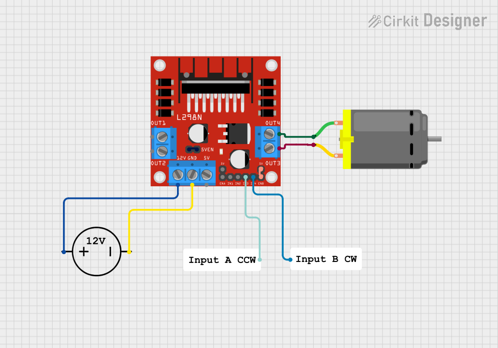
Motor Connections:
- For Motor A, connect its terminals to
OUT1andOUT2. - For Motor B, connect its terminals to
OUT3andOUT4.
- For Motor A, connect its terminals to
Control Connections:
- Connect the
IN1andIN2pins to your microcontroller to control Motor A's direction. - Connect the
IN3andIN4pins to your microcontroller to control Motor B's direction. - Use the
ENAandENBpins for speed control by providing a PWM signal.
- Connect the
Logic Power:
- If using an external 5V logic power source, connect it to the
5Vpin. Ensure the ground of the logic power source is connected to theGNDpin.
- If using an external 5V logic power source, connect it to the
Important Considerations
- Heat Dissipation: The L298N can get hot during operation. Use a heatsink or active cooling for high-current applications.
- Current Limitation: Ensure the motor's current does not exceed 2A per channel to avoid damage.
- Flyback Diodes: The L298N has built-in flyback diodes to protect against voltage spikes caused by motor inductance.
Example: Connecting to an Arduino UNO
Below is an example of how to control a DC motor using the L298N and an Arduino UNO:
Circuit Connections
- Connect
ENAto Arduino pin 9 (PWM output). - Connect
IN1to Arduino pin 8. - Connect
IN2to Arduino pin 7. - Connect the motor terminals to
OUT1andOUT2. - Connect the motor power supply to
VCCandGND.
Arduino Code
// L298N Motor Driver Example with Arduino UNO
// Controls a single DC motor connected to Motor A

#define ENA 9  // PWM pin for speed control
#define IN1 8  // Direction control pin 1
#define IN2 7  // Direction control pin 2

void setup() {
  // Set motor control pins as outputs
  pinMode(ENA, OUTPUT);
  pinMode(IN1, OUTPUT);
  pinMode(IN2, OUTPUT);
}

void loop() {
  // Rotate motor forward
  digitalWrite(IN1, HIGH);  // Set IN1 HIGH
  digitalWrite(IN2, LOW);   // Set IN2 LOW
  analogWrite(ENA, 150);    // Set speed (0-255)

  delay(2000);              // Run for 2 seconds

  // Rotate motor backward
  digitalWrite(IN1, LOW);   // Set IN1 LOW
  digitalWrite(IN2, HIGH);  // Set IN2 HIGH
  analogWrite(ENA, 150);    // Set speed (0-255)

  delay(2000);              // Run for 2 seconds

  // Stop motor
  digitalWrite(IN1, LOW);   // Set IN1 LOW
  digitalWrite(IN2, LOW);   // Set IN2 LOW
  analogWrite(ENA, 0);      // Set speed to 0

  delay(2000);              // Wait for 2 seconds
}
Troubleshooting and FAQs
Common Issues
Motor Not Spinning:
- Check the power supply voltage and ensure it matches the motor's requirements.
- Verify the connections to the
INandOUTpins. - Ensure the
ENAorENBpin is receiving a PWM signal or is set HIGH.
Overheating:
- Ensure the current drawn by the motor does not exceed 2A per channel.
- Use a heatsink or active cooling for high-current applications.
Noisy Motor Operation:
- Check for loose connections.
- Use capacitors across the motor terminals to reduce electrical noise.
FAQs
Q: Can the L298N control stepper motors?
A: Yes, the L298N can control a bipolar stepper motor by using both channels (Motor A and Motor B).
Q: Can I use the onboard 5V regulator to power my Arduino?
A: Yes, if the motor power supply is above 7V, the onboard 5V regulator can provide power to the Arduino. However, ensure the current draw does not exceed the regulator's capacity.
Q: What is the maximum PWM frequency supported?
A: The L298N supports PWM frequencies up to 20 kHz.
Q: Can I control more than two motors with one L298N?
A: No, the L298N can control only two DC motors or one stepper motor. For additional motors, use multiple L298N modules.