
How to Use USB Connectors: Examples, Pinouts, and Specs
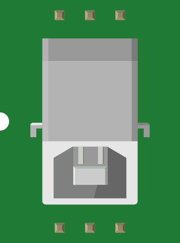
 Design with USB Connectors in Cirkit Designer
Introduction
USB connectors, manufactured by SparkFun (Part ID: PRT-00139), are standardized interfaces designed for connecting devices to computers, peripherals, and power sources. They facilitate data transfer and device charging, making them an essential component in modern electronics. These connectors are widely used in consumer electronics, embedded systems, and prototyping projects.
Explore Projects Built with USB Connectors
 Open Project in Cirkit Designer
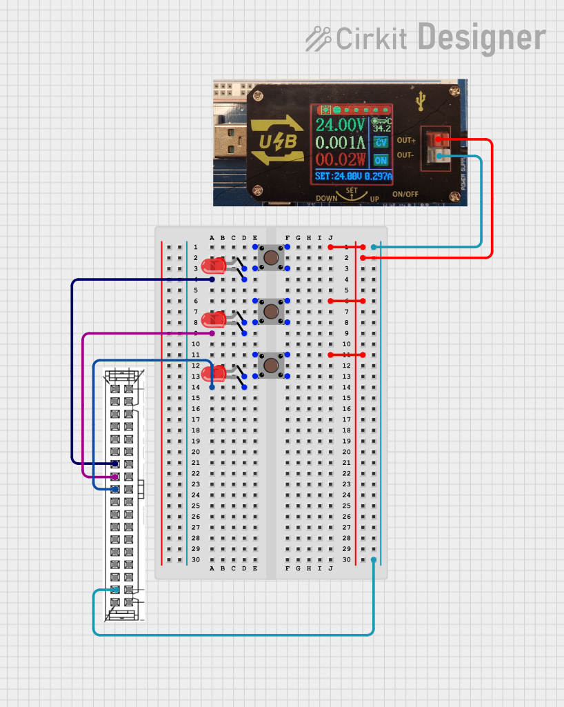 Open Project in Cirkit Designer
 Open Project in Cirkit Designer
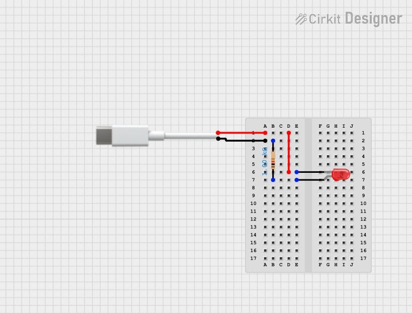 Open Project in Cirkit Designer
Explore Projects Built with USB Connectors
Open Project in Cirkit DesignerOpen Project in Cirkit DesignerOpen Project in Cirkit DesignerOpen Project in Cirkit DesignerCommon Applications and Use Cases
- Data Transfer: Connecting peripherals like keyboards, mice, and external storage devices to computers.
- Power Delivery: Charging devices such as smartphones, tablets, and wearables.
- Embedded Systems: Integrating USB connectivity in microcontroller-based projects.
- Prototyping: Building custom circuits and devices that require USB communication or power.
Technical Specifications
Below are the key technical details for the SparkFun USB Connector (PRT-00139):
General Specifications
- Connector Type: USB Type-B (Female)
- Voltage Rating: 5V DC
- Current Rating: Up to 1.5A
- Mounting Style: Through-hole
- Material: Nickel-plated contacts with a durable plastic housing
- Dimensions: 15.5mm x 13.5mm x 10.5mm (L x W x H)
Pin Configuration and Descriptions
The USB Type-B connector has four pins, as detailed in the table below:
| Pin Number | Name | Description |
|---|---|---|
| 1 | VBUS | +5V power supply |
| 2 | D- | Data line for differential signaling (negative) |
| 3 | D+ | Data line for differential signaling (positive) |
| 4 | GND | Ground connection |
Usage Instructions
How to Use the USB Connector in a Circuit
Mounting the Connector:
- Solder the through-hole pins of the USB connector onto a PCB.
- Ensure proper alignment to avoid misconnection or mechanical stress.
Connecting to a Microcontroller:
- Connect the VBUS pin to the 5V input of your circuit.
- Connect the GND pin to the ground plane of your PCB.
- Use the D- and D+ pins for data communication. These should be connected to the corresponding USB data pins on your microcontroller or USB interface IC.
Power Delivery:
- If using the connector for power delivery only, connect the VBUS and GND pins to your circuit's power input and ground, respectively.
Important Considerations and Best Practices
- Signal Integrity: Use short and properly routed traces for the D- and D+ lines to minimize noise and signal degradation.
- Decoupling Capacitors: Place a 0.1µF capacitor near the VBUS pin to filter out noise from the power supply.
- Mechanical Stability: Secure the connector to the PCB using screws or additional solder points to prevent damage from repeated plugging and unplugging.
- ESD Protection: Add ESD protection diodes on the D- and D+ lines to safeguard against electrostatic discharge.
Example: Connecting to an Arduino UNO
The USB connector can be used to power an Arduino UNO or enable serial communication. Below is an example of Arduino code for serial communication via USB:
// Example: Serial communication via USB
// This code sends a message to the serial monitor every second.

void setup() {
  Serial.begin(9600); // Initialize serial communication at 9600 baud
  while (!Serial) {
    // Wait for the serial port to connect (for boards like Leonardo)
  }
  Serial.println("USB Serial Communication Initialized");
}

void loop() {
  Serial.println("Hello, USB!"); // Send a message to the serial monitor
  delay(1000); // Wait for 1 second
}
Troubleshooting and FAQs
Common Issues Users Might Face
No Power or Data Transfer:
- Cause: Incorrect pin connections or poor soldering.
- Solution: Verify the pin connections and inspect solder joints for continuity.
Intermittent Connection:
- Cause: Loose or damaged connector.
- Solution: Ensure the connector is securely mounted and replace it if damaged.
Noise on Data Lines:
- Cause: Improper routing of D- and D+ traces.
- Solution: Use short, parallel traces with proper impedance matching.
Device Not Recognized by Computer:
- Cause: Missing or incorrect USB driver.
- Solution: Install the appropriate driver for your device or microcontroller.
Solutions and Tips for Troubleshooting
- Use a multimeter to check for continuity and proper voltage levels on the pins.
- Test the connector with a known working USB cable and device to isolate the issue.
- Inspect the PCB for any solder bridges or shorts between pins.
By following this documentation, users can effectively integrate and troubleshoot the SparkFun USB Connector (PRT-00139) in their projects.